�V�K�L���̓��e���s�����ƂŁA��\���ɂ��邱�Ƃ��\�ł��B
�L��
�V�K�L���̓��e���s�����ƂŁA��\���ɂ��邱�Ƃ��\�ł��B
posted by fanblog
2018�N08��13��
�y�ԊO��10�zGroovesizer mk1 / �u���b�h�{�[�h
Groovesizer mk1: DIY 16-step sequencer and synth
�O���"ARDUINO STEP SEQUENCER" ���������Ƃ��Ɉꏏ��Groovesizer mk1: DIY 16-step sequencer and synth�Ƃ����̂�������

"DIY 16-step sequencer and synth"�Ƃ̂��Ƃ�16�X�e�b�v�V�[�P���T�[�炵�����E�E�E�m�u�T�͂����Ƃ��ă{�^�����T��8LED��16�X�e�b�v�V�[�P���T�[���Ăǂ�Ȃ�H
���̃T�C�g�ɒu���Ă���YouTube�����ő�����@��������Ă�����܂����悭�킩��Ȃ�
�Ƃ����킯�ō���Ă݂�
Groovesizer mk1 Manual
���̃T�C�g��ǂނƂ��ꂪAuduino�����ɂ��Ă���炵�����Ƃ������Ă����āA������MANUAL���u���Ă���܂���
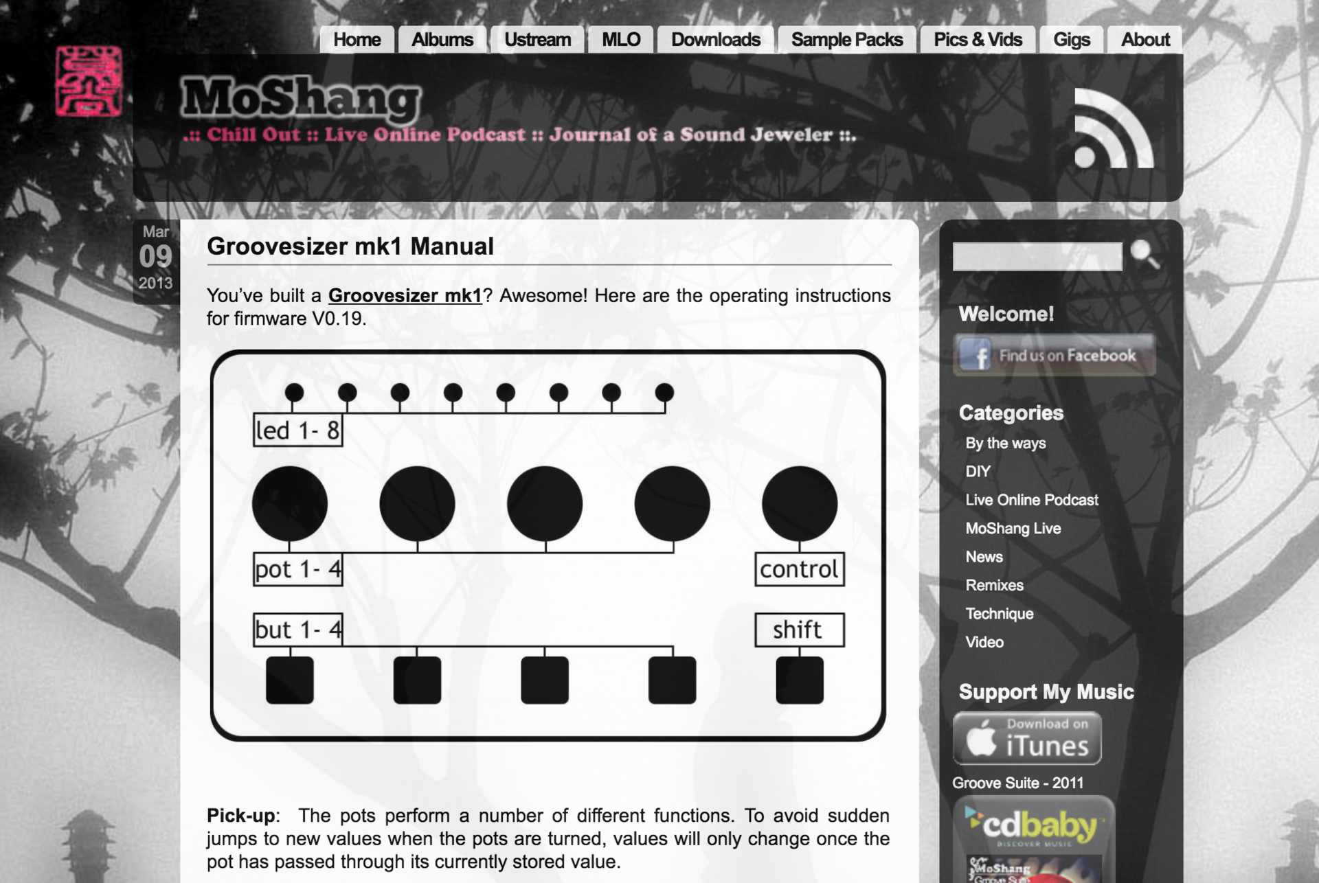
MANUAL��ǂނƂ��낢��ł��邱�Ƃ��킩��܂�
�f���炵���I
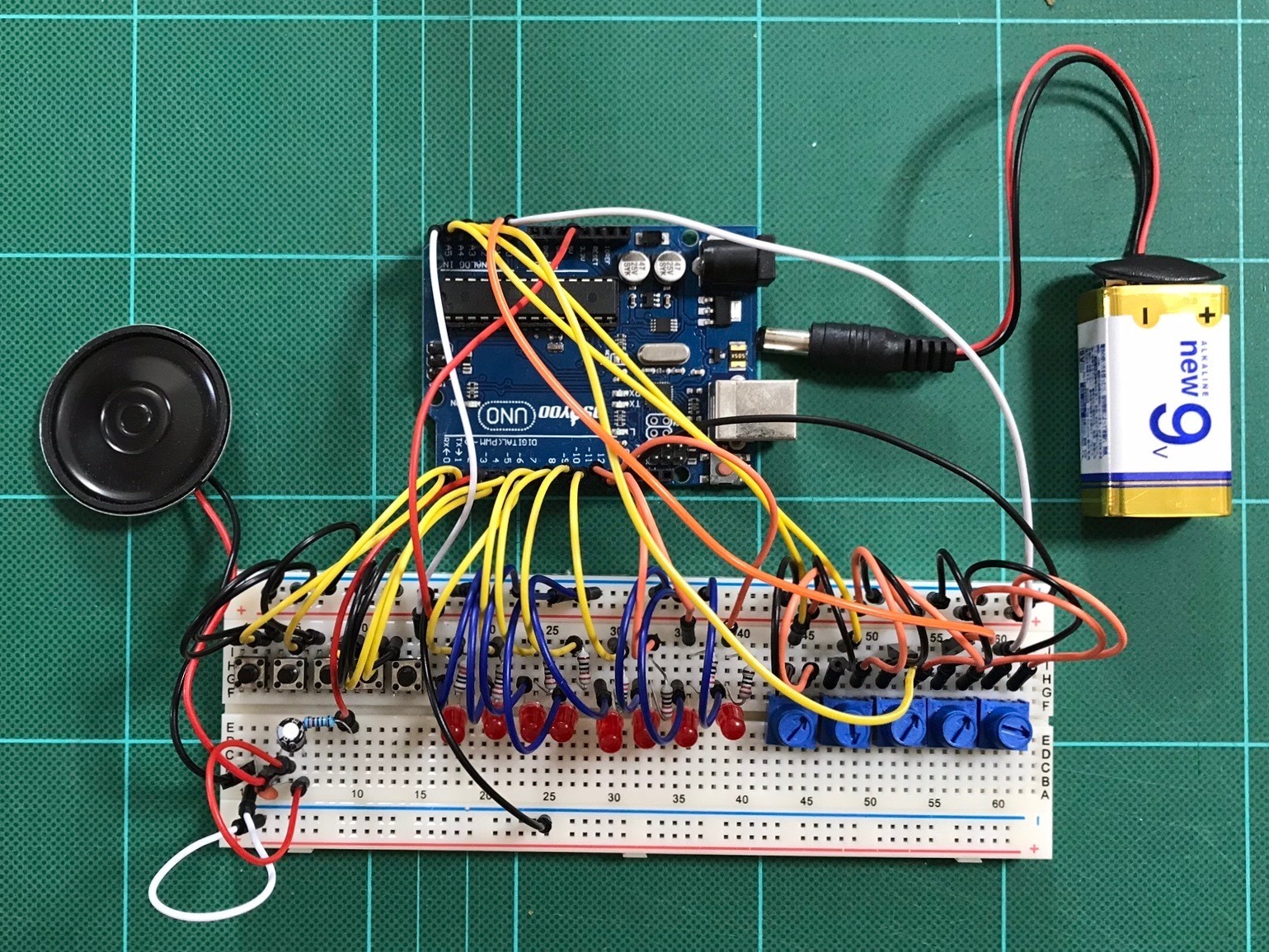
Groovesizer mk1 / �u���b�h�{�[�h
�u���b�h�{�[�h�Ŋm�F���܂�
�i�P�j�z��
����MIDI out�͔z�����܂���
�i�p�[�c�j
�@�@�@1. 2.2k�� ��R x1
�@�@�@2. 220�� ��R x9
�@�@�@3. 100nF �R���f���T�[ (104) x1
�@�@�@4. 100uF �R���f���T�[ x1
�@�@�@5. 5k�� �g���}�|�e���V�����[�^�[ x5
�@�@�@6. �^�N�g�X�C�b�` x5
�@�@�@7. 5mm LED x8
�@�@�@8. 8�� 0.5W�X�s�[�J�[ x1
�@�@�@9. Arduino UNO x1
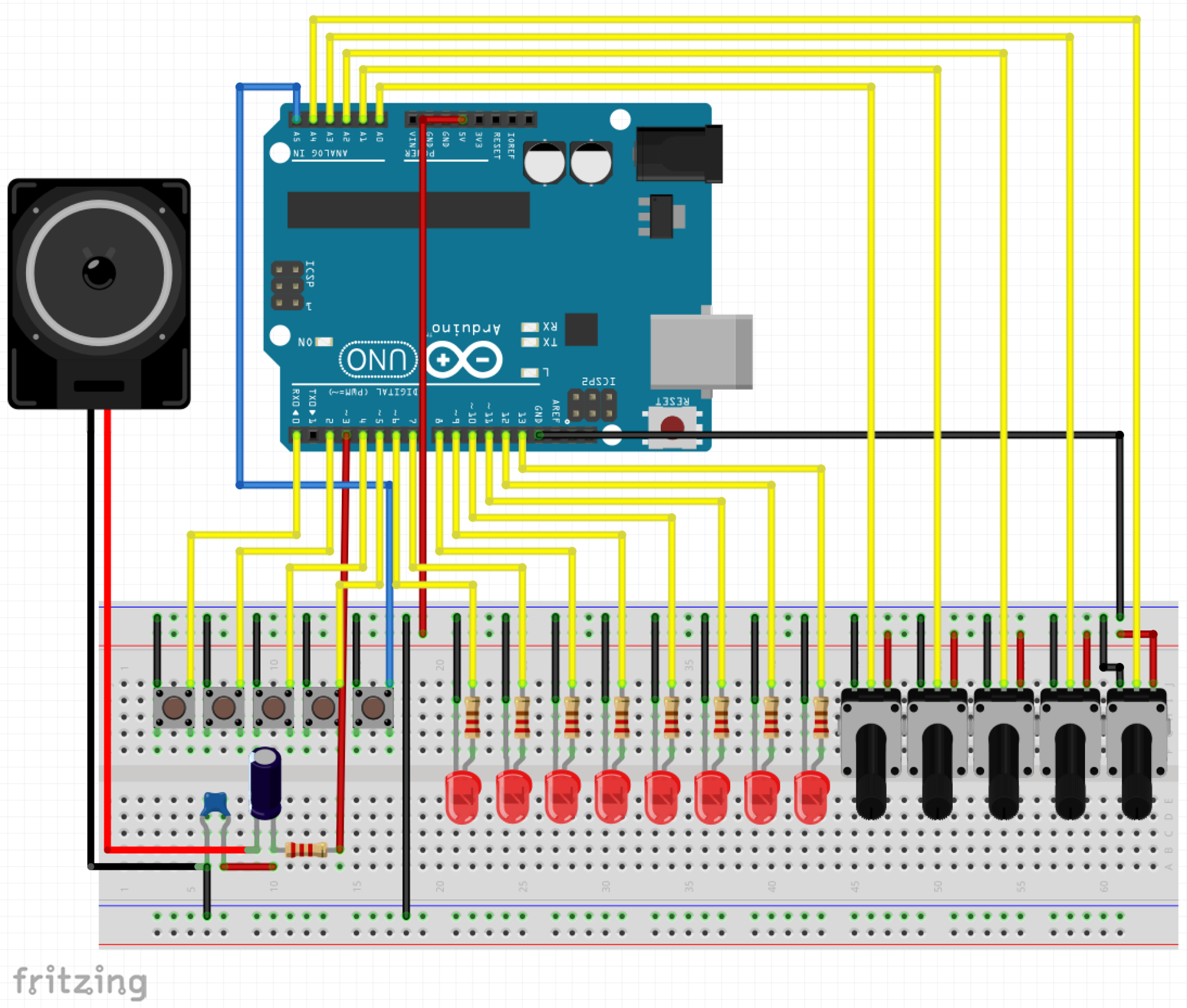
�i�Q�j�X�P�b�`
���̃X�P�b�`�͌��\���߂Ȃ̂�zip�t�@�C���̃_�E�����[�h�����N���u���Ă����܂�
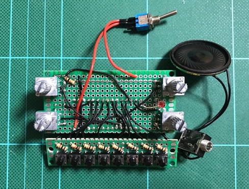
�i�R�j���s
���s���Ă݂܂������E�E�E
���̓���̗����
- ��L�̔z�������ł͉����قƂ�Ǖ������Ȃ�
- �R���f���T�[�����ăX�s�[�J�[�Ɍq���Ɗ�炩�͕������邯�ǖ����������ʂ��ᖳ��
- �Ȃ�ƃ{�����[���t���A���v�ɂȂ����狓������������
- ����AGroovesizer mk1�̃T�C�g�Ɠ������X�e���I�s���W���b�N�o�R�ŃX�s�[�J�[�Ɍq���ƁE�E�E�悭��������悤�ɂȂ�
�Ƃ��������ł���
�܂��A�͂��߂��珑����Ă���ʂ�ɍ��Ȃ����Ƃ������ƂȂ�ł����E�E�E
������~���g�ʂɓ��ꂽ�����ǁE�E�E���邩�ȁH
�ړI�������u�Ƃ肠�����~���g�T�C�Y�ʂɓ���Ă݂�v�ɂȂ��Ă����ȁE�E�E
�ł͂܂��`
 | �V�i���i |
 | Raspberry Pi3 Model B �{�[�h���P�[�X�Z�b�g (Element14��, Clear)-Physical Computing Lab �V�i���i |
 | Arduino���͂��߂悤 ��3�� (Make:PROJECTS) �V�i���i |
 | �V�i���i |
 | �V�i���i |
 | Arduino �G���g���[�L�b�g(Uno�Łj- Physical Computing Lab �V�i���i |
 | �^�~�� �y�����H��V���[�Y No.216 3ch RC���{�b�g����Z�b�g 70216 �V�i���i |
 | �G���L�b�g ���������{�b�g�A�[�� MR-9105 �V�i���i |
 | �G���L�b�g �o�g���^�C�^��2 MR-9101R �V�i���i |
 | �V�i���i |
 | �^�~�� �y�����H��V���[�Y No.211 �A�[���N���[���[�H��Z�b�g 70211 �V�i���i |
 | �^�~�� �y�����H��V���[�Y No.97 �c�C�����[�^�[�M���[�{�b�N�X (70097) �V�i���i |
 | �^�~�� �y�����H��V���[�Y No.106 4�`�����l���E�����R���{�b�N�X (70106) �V�i���i |


2018�N08��06��
�y�ԊO�҂X�zARDUINO STEP SEQUENCER / �~���g��
ARDUINO STEP SEQUENCER
�O�������T�C�g(https://www.instructables.com/id/Arduino-Step-Sequencer/)���Q�l��"ARDUINO STEP SEQUENCER"���u���b�h�{�[�h�ɂăe�X�g���܂���
����̓~���g�ʂɑg�݂܂�
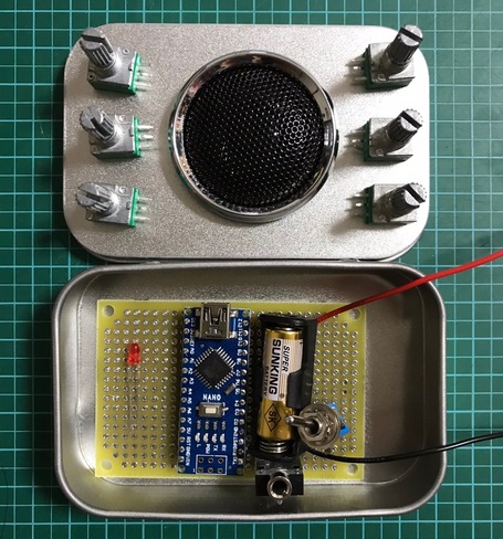
ARDUINO STEP SEQUENCER / �~���g��
�~���g�ʂőg�݂₷���悤�ɏ����p�[�c��ς��āAArduino UNO����Arduino NANO�ɕύX���܂�
�i�p�[�c�j
�@�@1. �^�N�g�X�C�b�` X8
�@�@2. �g�O���X�C�b�` X1
�@�@3. 3mm LED X1
�@�@4. 10K�� ��R X9
�@�@5. 10K �|�e���V�����[�^�[ X4
�@�@6. 8�� 2W �X�s�[�J�[ X1
�i�P�j�z��
�|�e���V�����[�^�[���m�u�ƃ^�N�g�X�C�b�`���{�^�����~���g�ʂ̊W����o��悤�Ɂi�P�j�|�e���V�����[�^�[�Ɓi�Q�j�^�N�g�X�C�b�`���ڂ�����ʂɂ��ĂQ���\���ɂ��܂���
���
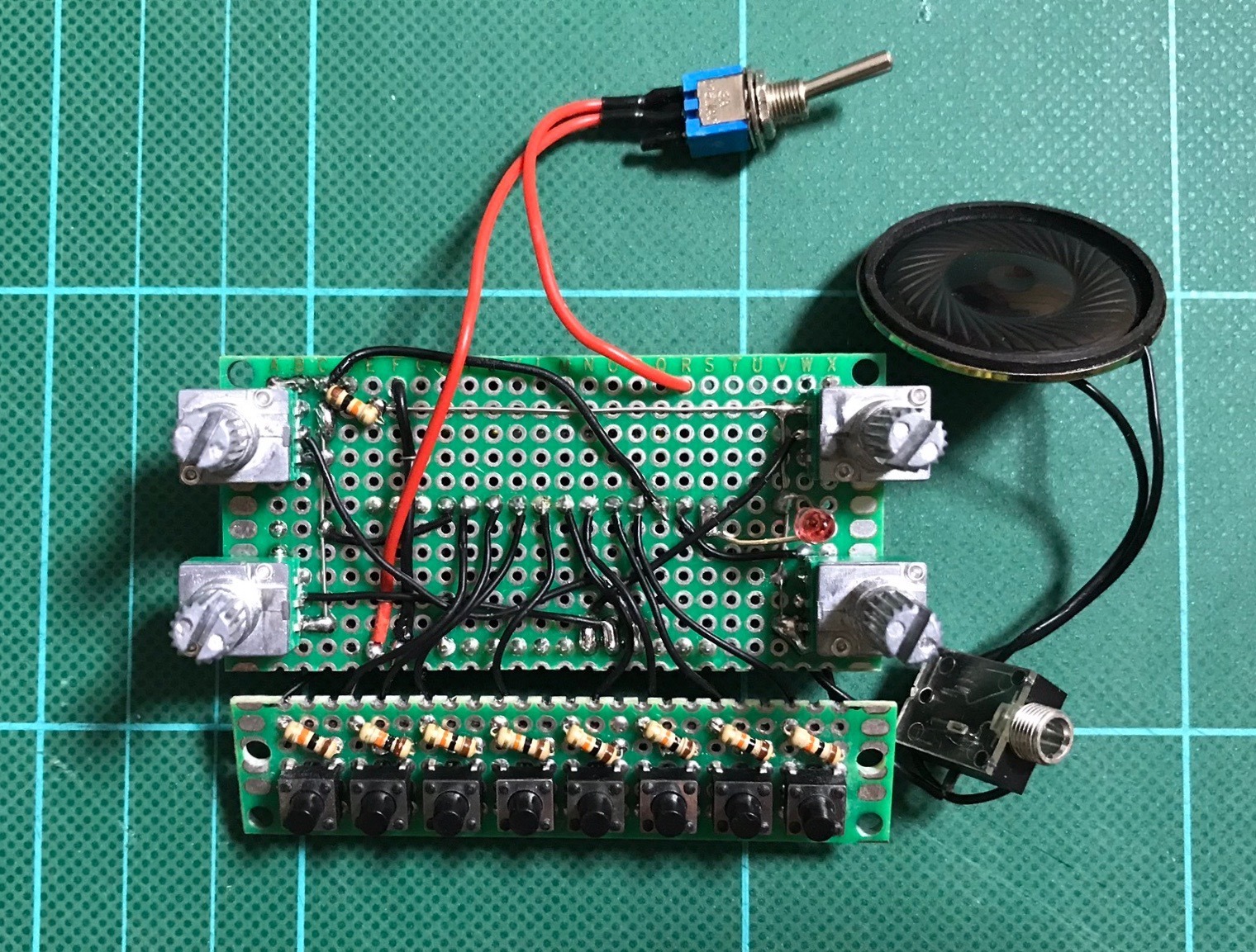
����

�Q���\��

�������ŁA�{�^���̒��`���^�N�g�X�C�b�`���g�����Ă�������������ȂƋC���t����
�i�Q�j�X�P�b�`
�X�P�b�`�͑O��ƈꏏ
�i�R�j�g�ݗ���
����e�X�g�����Ă���~���g�ʂɓ���āA����ɓ���e�X�g�����Ă��܂�
��ʐ}

�ߐ}

����łЂƂ܂������ł�
�ł͂܂��`
| �V�i���i |
| Raspberry Pi3 Model B �{�[�h���P�[�X�Z�b�g (Element14��, Clear)-Physical Computing Lab �V�i���i |
| Arduino���͂��߂悤 ��3�� (Make:PROJECTS) �V�i���i |
| �V�i���i |
| �V�i���i |
| Arduino �G���g���[�L�b�g(Uno�Łj- Physical Computing Lab �V�i���i |
| �^�~�� �y�����H��V���[�Y No.216 3ch RC���{�b�g����Z�b�g 70216 �V�i���i |
| �G���L�b�g ���������{�b�g�A�[�� MR-9105 �V�i���i |
| �G���L�b�g �o�g���^�C�^��2 MR-9101R �V�i���i |
| �V�i���i |
| �^�~�� �y�����H��V���[�Y No.211 �A�[���N���[���[�H��Z�b�g 70211 �V�i���i |
| �^�~�� �y�����H��V���[�Y No.97 �c�C�����[�^�[�M���[�{�b�N�X (70097) �V�i���i |
| �^�~�� �y�����H��V���[�Y No.106 4�`�����l���E�����R���{�b�N�X (70106) �V�i���i |
2018�N07��31��
�y�ԊO�҂W�zARDUINO STEP SEQUENCER / �u���b�h�{�[�h
ARDUINO STEP SEQUENCER
����Arduino�ŃX�e�b�v�V�[�P���T�[����肽���Ǝv���ăO�O���Ă���A���̖���"ARDUINO STEP SEQUENCER" �̃T�C�g��������
"A simple programmable 8 step tone sequencer"�Ƃ̂��ƂŁAtone�@�\���g����8�X�e�b�v�V�[�P���T�[�炵��
�܂������̃T�C�g�ihttp://www.instructables.com/id/Arduino-Step-Sequencer/�j ���Q�l�Ƀu���b�h�{�[�h�őg��ł݂܂�
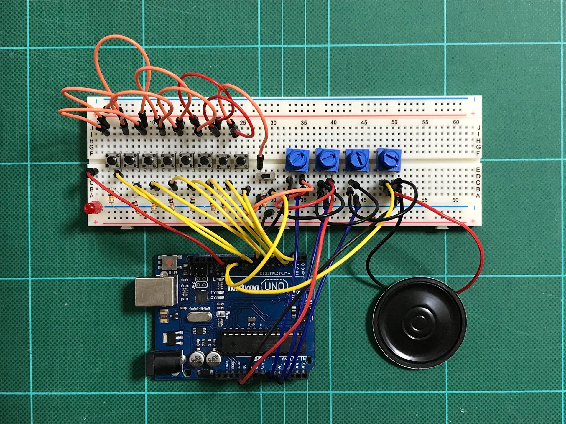
ARDUINO STEP SEQUENCER / �u���b�h�{�[�h
�u���b�h�{�[�h�őg�݂₷���悤�ɏ����p�[�c��ς���
�i�p�[�c�j
�@�@1. �^�N�g�X�C�b�` X8
�@�@2. �X���C�h�X�C�b�` X1
�@�@3. LED X1
�@�@4. 10K�� ��R X9
�@�@5. 100K �g���}�|�e���V�����[�^�[ X4
�@�@6. 8�� 0.5W �X�s�[�J�[ X1
�i�P�j�z��
�z���͂���Ȋ���
�i�Q�j�X�P�b�`
�X�P�b�`��"ARDUINO STEP SEQUENCER"�̃T�C�g ���炻�̂܂܃R�s�[���Ďg���ƃG���[���o��̂Ŏ��̂Q�ӏ������������Ďg��
�@�i�C���O�j
�@�@�@Serial.print (254, BYTE);
�@�@�@Serial.print (192, BYTE);
�@�i�C����j
�@�@�@Serial.print (254);
�@�@�@Serial.print (192);
�ŁA�C�������̂����ꁫ
Arduino Step Sequencer
�\�\�\�\�\�\�\�\�\�\(Arduino Step Sequencer)�\�\�\�\�\�\�\�\�\�\
/* ======================================================================
Arduino Punk Console
A simple programmable 8 step tone sequencer
by dano/beavisaudio.com
Revs
-----------------------------------
15 Sept djh initial version
======================================================================*/
// Map all the input and output pins
#define AnalogInFrequency 1
#define AnalogInTempo 2
#define AnalogInDuration 0
#define DigitalOutSignal 11
#define DigitalInSwitch0 2
#define DigitalInSwitch1 3
#define DigitalInSwitch2 4
#define DigitalInSwitch3 5
#define DigitalInSwitch4 6
#define DigitalInSwitch5 7
#define DigitalInSwitch6 8
#define DigitalInSwitch7 9
#define DigitalInStartStop 10
#define DigitalOutLED 12
// Set up the array for each step
int steps[] = {100,120,140,160,180,200,220,240};
// misc housekeeping
int duration = 50;
int pitchval = 1;
int fPlayMode = true;
int lastPushedStep = -1;
// Initialize the tempo
int tempo = 100;
void setup()
{
// setup pin modes (Digital pins are input by default, but
// I like to set 'em explicitly just so the code is clear.
pinMode (DigitalInSwitch0, INPUT);
pinMode (DigitalInSwitch1, INPUT);
pinMode (DigitalInSwitch2, INPUT);
pinMode (DigitalInSwitch3, INPUT);
pinMode (DigitalInSwitch4, INPUT);
pinMode (DigitalInSwitch5, INPUT);
pinMode (DigitalInSwitch6, INPUT);
pinMode (DigitalInSwitch7, INPUT);
pinMode (DigitalInStartStop, INPUT);
pinMode (DigitalOutSignal, OUTPUT);
pinMode (DigitalOutLED, OUTPUT);
}
void loop()
{
// Main sequence loop
for (int i=0; i<8; i++)
{
// Are we playing or stopping?
fPlayMode = digitalRead (DigitalInStartStop);
digitalWrite (DigitalOutLED, HIGH);
// Check the Hardware
readSwitches();
readPots();
// update the display
updateDisplay();
// Make the noise
if (fPlayMode)
{
freqout (steps[i], duration);
}
digitalWrite (DigitalOutLED, LOW);
// Pause between steps
delay (tempo);
}
}
void updateDisplay()
{
Serial.print (254);
Serial.print (192);
Serial.print ("T:");
Serial.print (tempo);
Serial.print (" d:");
Serial.print (duration);
if (lastPushedStep != -1)
{
Serial.print ("*");
Serial.print (lastPushedStep);
}
}
// Read the current values of the pots, called from the loop.
void readPots ()
{
tempo = (analogRead (AnalogInTempo) * 1.9);
duration = (analogRead (AnalogInDuration));
}
// Read the current values of the switches and
// if pressed, replace the switch's slot frequency
// by reading the frequency pot.
void readSwitches()
{
// reset last pushed button number
lastPushedStep = -1;
// check switch 0, if pressed, get the current freq into step 0, etc. etc.
if (digitalRead (DigitalInSwitch0) == HIGH)
{
steps[0] = analogRead(AnalogInFrequency);
lastPushedStep = 1;
}
else if (digitalRead (DigitalInSwitch1) == HIGH)
{
steps[1] = analogRead(AnalogInFrequency);
lastPushedStep = 2;
}
else if (digitalRead (DigitalInSwitch2) == HIGH)
{
steps[2] = analogRead(AnalogInFrequency);
lastPushedStep = 3;
}
else if (digitalRead (DigitalInSwitch3) == HIGH)
{
steps[3] = analogRead(AnalogInFrequency);
lastPushedStep = 4;
}
else if (digitalRead (DigitalInSwitch4) == HIGH)
{
steps[4] = analogRead(AnalogInFrequency);
lastPushedStep = 5;
}
else if (digitalRead (DigitalInSwitch5) == HIGH)
{
steps[5] = analogRead(AnalogInFrequency);
lastPushedStep = 6;
}
else if (digitalRead (DigitalInSwitch6) == HIGH)
{
steps[6] = analogRead(AnalogInFrequency);
lastPushedStep = 7;
}
else if (digitalRead (DigitalInSwitch7) == HIGH)
{
steps[7] = analogRead(AnalogInFrequency);
lastPushedStep = 8;
}
}
//freqout code by Paul Badger
// freq - frequency value
// t - time duration of tone
void freqout(int freq, int t)
{
int hperiod; //calculate 1/2 period in us
long cycles, i;
// subtract 7 us to make up for digitalWrite overhead - determined empirically
hperiod = (500000 / ((freq - 7) * pitchval));
// calculate cycles
cycles = ((long)freq * (long)t) / 1000; // calculate cycles
for (i=0; i<= cycles; i++)
{ // play note for t ms
digitalWrite(DigitalOutSignal, HIGH);
delayMicroseconds(hperiod);
digitalWrite(DigitalOutSignal, LOW);
delayMicroseconds(hperiod - 1); // - 1 to make up for fractional microsecond in digitaWrite overhead
}
}
�\�\�\�\�\�\�\�\�\�\�\�\�\�\�\�\�\�\�\�\�\�\�\�\�\�\�\
�i�R�j���s
�����A�ǂ��ł��傤
���삪�O�_�O�_�E�E�E
����������ƒP���ł����A�X�e�b�v�V�[�P���T�[���ۂ��Ȃ��Ă܂�
�V���Z�Ƃ͂܂�������ʔ����ł����E�E�E�v�����悤�ɑ���ł��܂���E�E�Eorz
���ƁA�Ȃς��ȂƎv���Ă���ł����ALED�\���������̂łǂ̃{�^���̉����Ȃ��Ă���̂��킩��ɂ���
����͂����➑̂ɓ���Ă݂܂�
�ł͂܂��`
| �V�i���i |
| Raspberry Pi3 Model B �{�[�h���P�[�X�Z�b�g (Element14��, Clear)-Physical Computing Lab �V�i���i |
| Arduino���͂��߂悤 ��3�� (Make:PROJECTS) �V�i���i |
| �V�i���i |
| �V�i���i |
| Arduino �G���g���[�L�b�g(Uno�Łj- Physical Computing Lab �V�i���i |
| �^�~�� �y�����H��V���[�Y No.216 3ch RC���{�b�g����Z�b�g 70216 �V�i���i |
| �G���L�b�g ���������{�b�g�A�[�� MR-9105 �V�i���i |
| �G���L�b�g �o�g���^�C�^��2 MR-9101R �V�i���i |
| �V�i���i |
| �^�~�� �y�����H��V���[�Y No.211 �A�[���N���[���[�H��Z�b�g 70211 �V�i���i |
| �^�~�� �y�����H��V���[�Y No.97 �c�C�����[�^�[�M���[�{�b�N�X (70097) �V�i���i |
| �^�~�� �y�����H��V���[�Y No.106 4�`�����l���E�����R���{�b�N�X (70106) �V�i���i |
2018�N07��17��
�y�ԊO�҂U�zSimple_Four-Step_Sequencer (S4SS) / �~���g��
Simple_Four-Step_Sequencer
�O��Simple_Two-Step_Sequencer�Ƃ���Arduino�V���Z�������ς���Simple_Two-Step_Sequencerx2��Simple_Five-Step_Sequencer�Ƃ����̂ɂ��Ă݂�
�����Auduino_v5�Ɠ����悤�Ƀ~���g�ʂɓ���悤�Ǝv�����̂����ǃX�y�[�X�I�ɂ�����ƌ�����
�����Simple_Five-Step_Sequencer����I�V���[�^�[���P���炵��Simple_Four-Step_Sequencer�@(S4SS)������
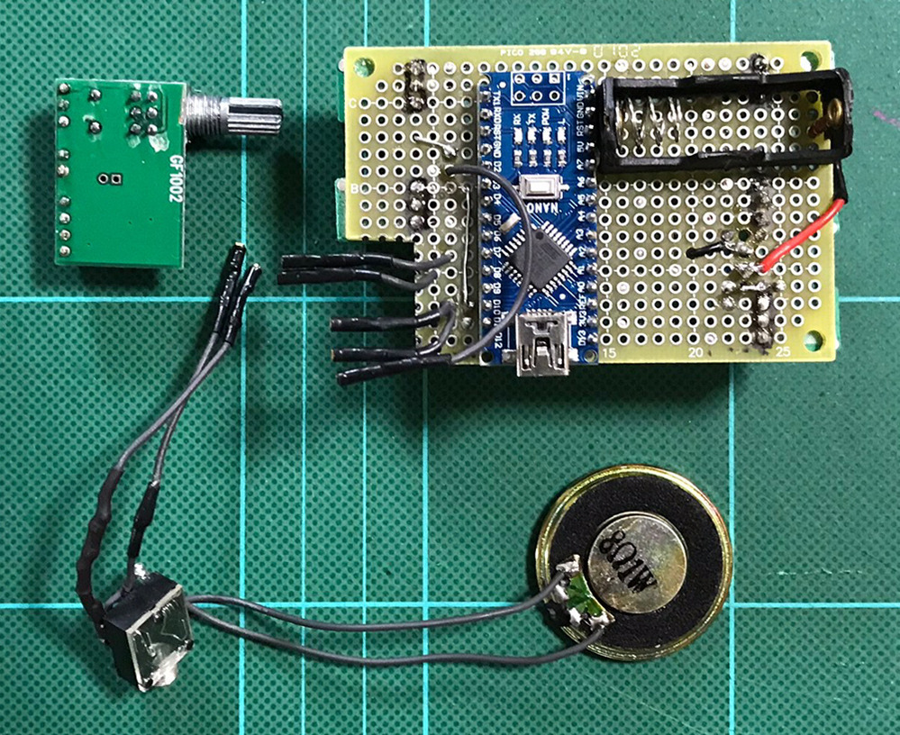
S4SS / �~���g��
�p�[�c��Arduino_v5 / �~���g�ʂƂقƂ�Ǔ��������ǃA���v���j�b�g���Ȃ��������y�ɂł���͂�
����͓d���X�C�b�`�ƃI�[�f�B�I�W���b�N���W�ɂ�����
���Ȃ݂ɃX�P�b�`��Simple_Five-Step_Sequencer�̂��̂����̂܂g���ĂT�ڂ̃I�V���[�^�[�p�m�u����������
�i1�j�p�[�c�z�u
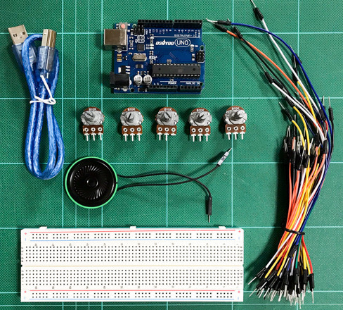
�p�[�c
�@�@1. �~���g�� x1
�@�@2. Arduino NANO x1
�@�@3. 19k�����^�|�e���V�����[�^�[ x6
�@�@4. 12v�d�r�{�P�[�X x1
�@�@5. ���j�o�[�T����� x1
�@�@6. 5�s�� �X�e���I�I�[�f�B�I�W���b�N x1
�@�@7. �g�O���X�C�b�` x1
�@�@8. 3mm LED x1
�@�@9. 8�� 2W �X�s�[�J�[�{�X�s�[�J�[�O���� x1
�p�[�c�̔z�u�͂���Ȋ���

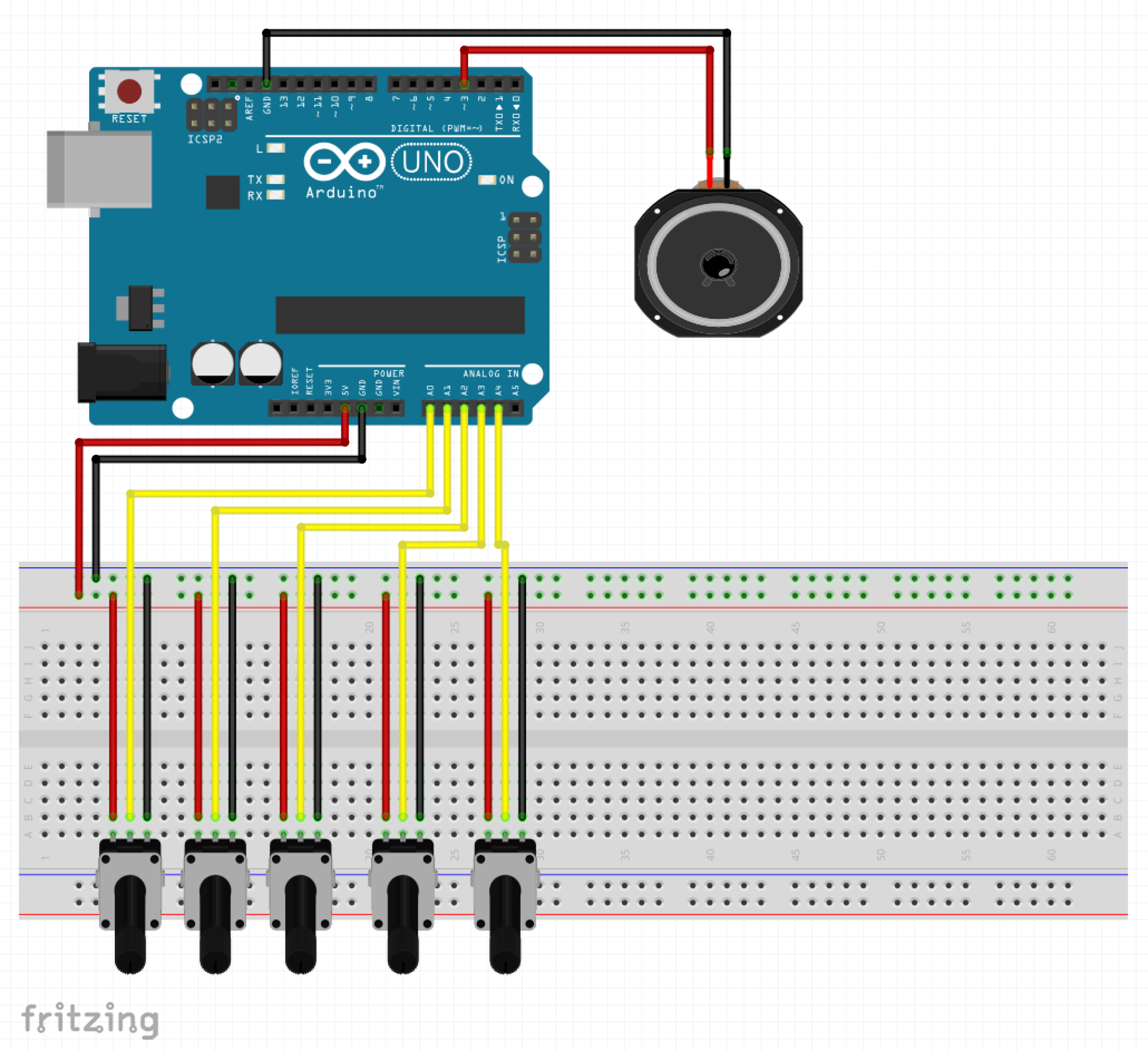
�i2�j�z��
�O��̃u���b�h�{�[�h�e�X�g�����Ƀ��j�o�[�T����ɔz�����܂���
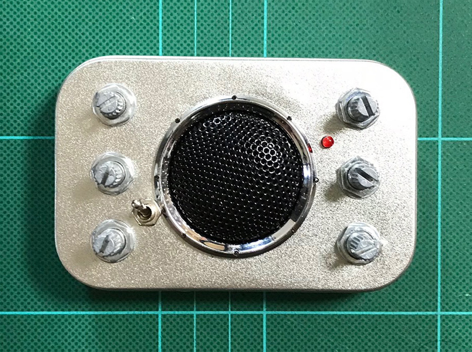
���

����

�i3�j�g�ݗ���
�ł́A�~���g�ʂɑg�ݓ���܂�
�ł��܂�������

Auduino_v5�Ƌ�ʂ����ɂ����E�E�E
��`�A����I�V���[�^�[�P���炵�����ǁE�E�E����ς�t���o�[�V�������������ȁ`
�ł͂܂��`
| �V�i���i |
| Raspberry Pi3 Model B �{�[�h���P�[�X�Z�b�g (Element14��, Clear)-Physical Computing Lab �V�i���i |
| Arduino���͂��߂悤 ��3�� (Make:PROJECTS) �V�i���i |
| �V�i���i |
| �V�i���i |
| Arduino �G���g���[�L�b�g(Uno�Łj- Physical Computing Lab �V�i���i |
| �^�~�� �y�����H��V���[�Y No.216 3ch RC���{�b�g����Z�b�g 70216 �V�i���i |
| �G���L�b�g ���������{�b�g�A�[�� MR-9105 �V�i���i |
| �G���L�b�g �o�g���^�C�^��2 MR-9101R �V�i���i |
| �V�i���i |
| �^�~�� �y�����H��V���[�Y No.211 �A�[���N���[���[�H��Z�b�g 70211 �V�i���i |
| �^�~�� �y�����H��V���[�Y No.97 �c�C�����[�^�[�M���[�{�b�N�X (70097) �V�i���i |
| �^�~�� �y�����H��V���[�Y No.106 4�`�����l���E�����R���{�b�N�X (70106) �V�i���i |
2018�N07��10��
�y�ԊO�҂T�zSimple_Two-Step_Sequencer (STSS) / �u���b�h�{�[�h
Workshop: Basic Arduino Square-Wave Synth
�O��܂�Auduino_v5�������ς����肵�Ă݂����ǁA����ȏ�͎����悤�ȃA�C�f�A�����Ȃ�
�ق���Arduino�V���Z�����������̂ŕʂ̂��̂�����Ă݂�
�O�O���Ă���"Workshop: Basic Arduino Square-Wave Synth"�Ƃ����T�C�g��������
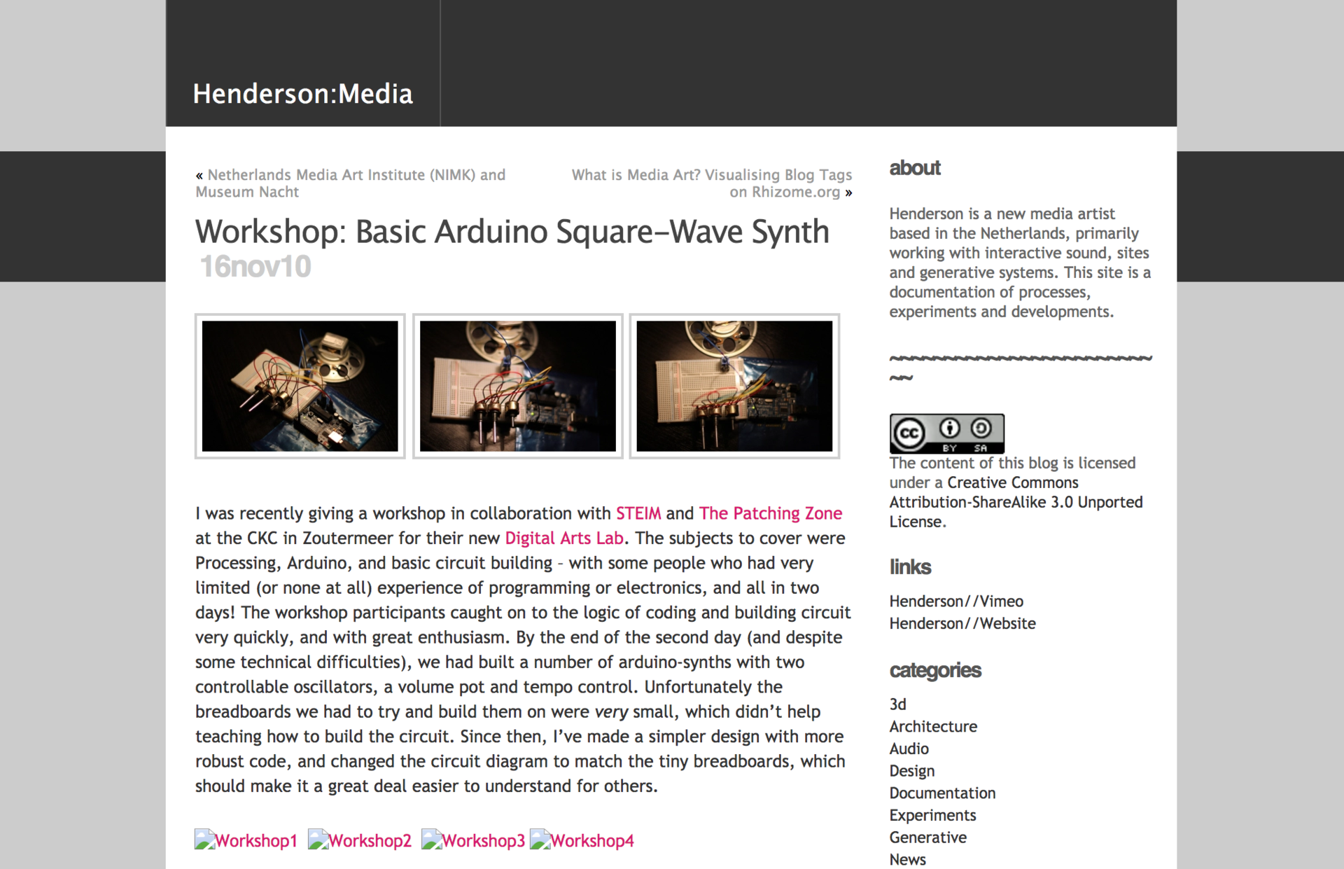
������Workshop�l�^�炵���̂ł��₷�����ȂƎv�������ǁA���̃V���Z�̉���������Ȃ������̂łǂ�ȉ����o��̂��킩��Ȃ�
�ŁA�Ƃ肠���������Ă���l����
�P. Simple_Two-Step_Sequencer (STSS)
�i�P�j�z��
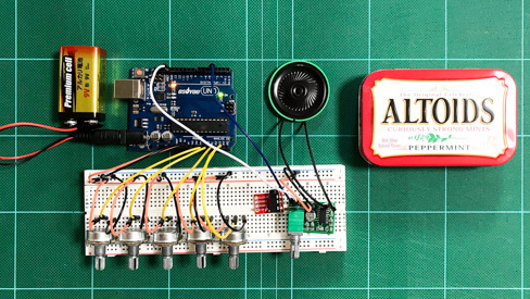
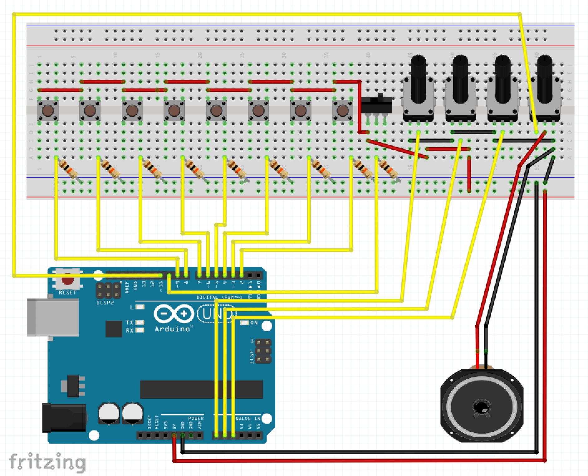
�܂��̓u���b�h�{�[�h�ł̔z��
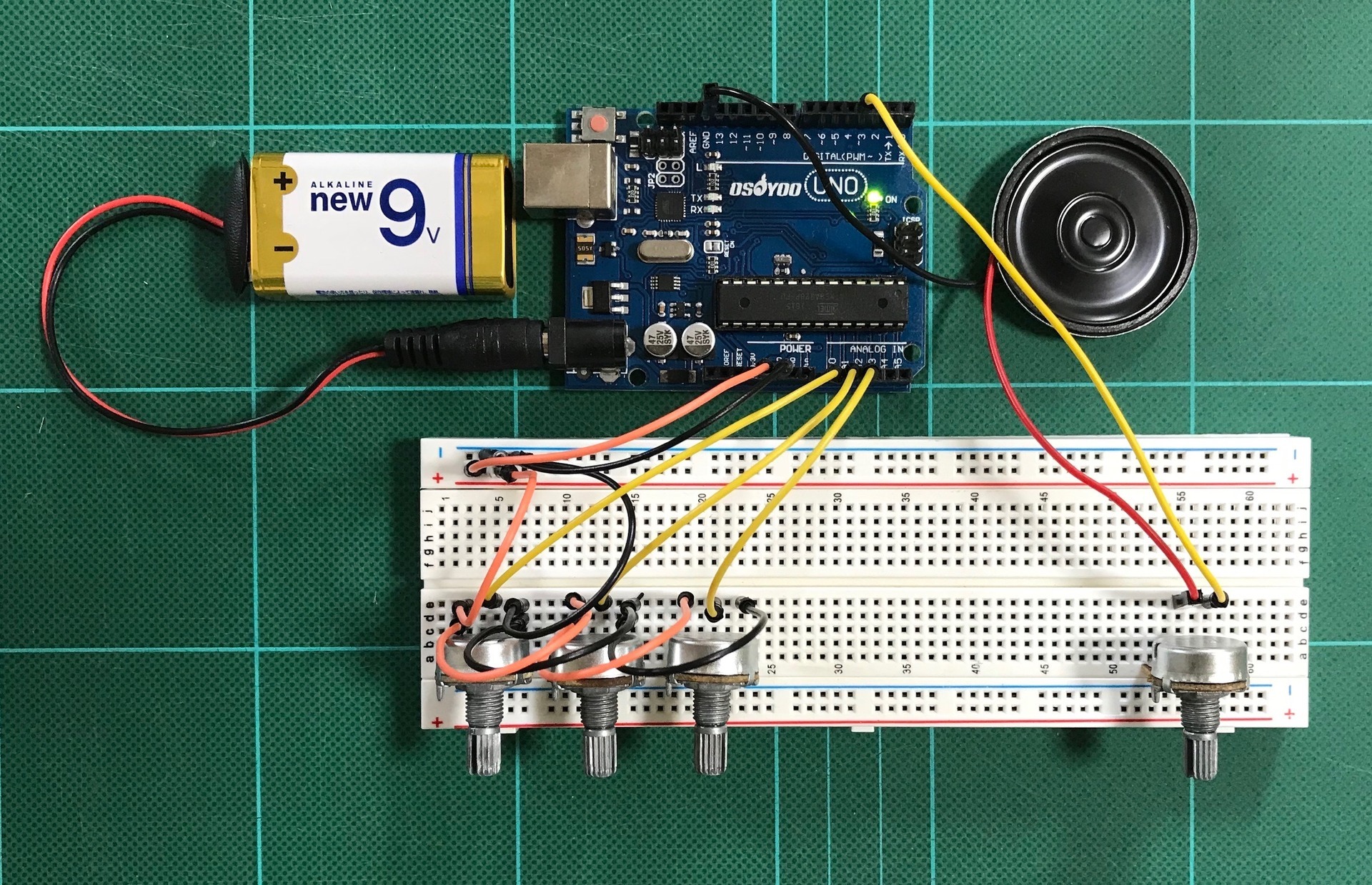
Fritzing��
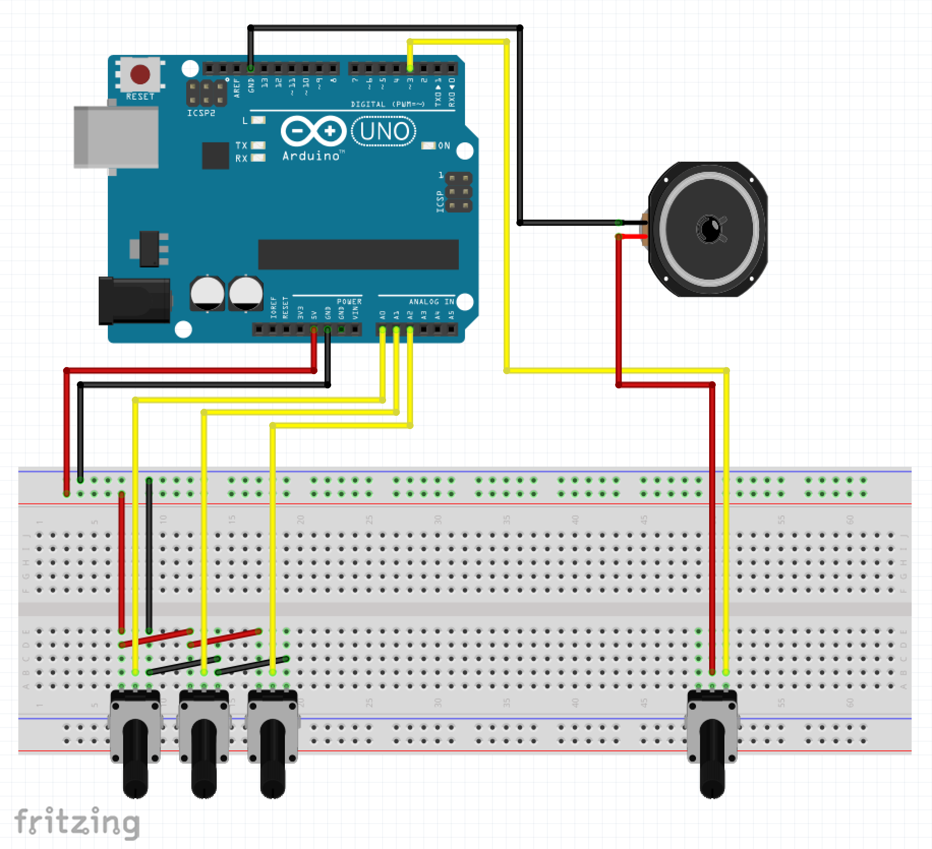
����A�|�e���V����10k�����g���Ă܂�
�i�Q�j�X�P�b�`
�X�P�b�`��"Workshop: Basic Arduino Square-Wave Synth"����R�s�y
Simple_Two-Step_Sequencer (STSS)
�\�\�\�\�\�\�\(Simple_Two-Step_Sequencer)�\�\�\�\�\�\�\
/*
6: Simple Two-Step Sequencer
This project combines pretty much everything from the previous tutorials.
It involves two oscillators, a status led, and tempo and volume pots.
*/
int speakerPin = 3; //connect speaker to pin 3
int ledPin = 11; //we'll use this pin for our status led
int oscillator1Pin = 0; //we can set frequency for first step here...
int oscillator2Pin = 1; //... and frequency for step 2 on this pin
int tempoPin = 2; //read tempo pot here
/*
The pinState variable checks if we are outputting a sound.
By default we can set it to LOW - meaning "off".
*/
int pinState = LOW;
long previousMicros; //count microSeconds to control frequency
int frequency; //variable to set frequency
long previousMillis; //count milliSeconds to control tempo
int tempo = 120; //default tempo is 120BPM
void setup(){
Serial.begin(9600);
pinMode(speakerPin, OUTPUT);
}
void loop(){
//read from our analog pins and set our frequency limits
float oscillator1 = analogRead(oscillator1Pin);
oscillator1 = map(oscillator1, 0, 1023, 200, 2000);
float oscillator2 = analogRead(oscillator2Pin);
oscillator2 = map(oscillator2, 0, 1023, 200, 2000);
//read and set tempo limits
float tempo = analogRead(tempoPin);
tempo = map(tempo, 0, 1023, 60, 1000);
//algorithm to convert tempo into BPM
float interval = (1000/tempo)*60;
/*
We can't use the delay function in this case,
as it will freeze the sketch and disrupt the
oscillators.
Instead we use a method that counts milliSeconds,
compares it to our BPM, and switches between which
oscillator should be in use.
*/
//oscillator1
if(millis()-previousMillis > interval/2){
playTone(speakerPin, oscillator1, interval/2);
analogWrite(ledPin, LOW);
}
//oscillator 2
if(millis()-previousMillis < interval/2){
playTone(speakerPin, oscillator2, interval/2);
analogWrite(ledPin, tempo/4);
}
//One cycle completed: reset our counter!
if(millis()-previousMillis > interval){
previousMillis = millis();
}
}
/*
We use the same method here as above to
switch our outputPin on and off without having
to use delay() and thus keep everything running
smoothly.
*/
void playTone(int outputPin, int frequency, float tempo){
//this bit is new - it makes sure we're calculating the note's frequency correctly
float hperiod = (500000 / frequency) -7;
long cycles = ((frequency*tempo)/1000);
for(long i=0; i<=cycles; i++){
//we use frequency/2 because one LOW + one HIGH = one whole cycle
if(micros() - previousMicros > frequency/2){
previousMicros = micros();
if(pinState == LOW){
pinState = HIGH; //if the pin is already LOW, set it to HIGH
}
else{
pinState = LOW; //otherwise if it's HIGH, set it to LOW
}
digitalWrite(outputPin, pinState); //Write pinState to specified pin
}
}
}
�\�\�\�\�\�\�\�\�\�\�\�\�\�\�\�\�\�\�\�\�\�\�\�\�\�\�\�\
�i�R�j���s
���܂�
�Ȃ�قǁE�E�E�̂̃A�j���̌��ʉ��݂����ȉ����o�Ă��܂����ˁE�E�E
�v���Ă���Ƃ����[�����Ċ����ł�������͂����
�ŁA����ŏI������Ⴄ��"Workshop: Basic Arduino Square-Wave Synth"�̏d�����ʂɑ��₵�������Ȃ̂ŏ����ς��܂�
�Q. Simple_Two-Step_Sequencerx2 (STSSx2)
Auduino_v5�̎��ɂQ�{�����܂�������������܂�
Arduino UNO�ɂ͂U�̃A�i���O�C���v�b�g������܂����ASTSS�̓I�V���[�^�[�Q�ƃe���|�P�ō��킹�ĂR�̃A�i���O�C���v�b�g���g���Ă��܂�
����͂���������P�Z�b�g�t�������邾���ł�
�Ƃ����킯�Ŗ��O��Simple_Two-Step_Sequencerx2
�i�P�j�z��
�u���b�h�{�[�h��ł̔z���͂���Ȋ���


�i�Q�j�X�P�b�`
�X�P�b�`�͏������������Ă���Ȋ���
Simple_Two-Step_Sequencerx2
�\�\�\�\�\(Simple_Two-Step_Sequencerx2 (STSSx2))�\�\�\�\�\
/*
6': Simple Two-Step Sequencer x2
This project combines pretty much everything from the previous tutorials.
It involves two oscillators, a status led, and tempo and volume pots.
Changelog:
It involves four oscillators, a status led, and two tempo and volume pots.
*/
int speakerPin = 3; //connect speaker to pin 3
int ledPin = 11; //we'll use this pin for our status led
int oscillator1Pin = 0; //we can set frequency for first step here...
int oscillator2Pin = 1; //... and frequency for step 2 on this pin
int tempoPin1 = 2; //read tempo pot here
int oscillator3Pin = 3; //we can set frequency for first step here...
int oscillator4Pin = 4; //... and frequency for step 2 on this pin
int tempoPin2 = 5; //read tempo pot here
/*
The pinState variable checks if we are outputting a sound.
By default we can set it to LOW - meaning "off".
*/
int pinState = LOW;
long previousMicros; //count microSeconds to control frequency
int frequency; //variable to set frequency
long previousMillis; //count milliSeconds to control tempo
int tempo = 120; //default tempo is 120BPM
void setup(){
Serial.begin(9600);
pinMode(speakerPin, OUTPUT);
}
void loop(){
//read from our analog pins and set our frequency limits
float oscillator1 = analogRead(oscillator1Pin);
oscillator1 = map(oscillator1, 0, 1023, 200, 2000);
float oscillator2 = analogRead(oscillator2Pin);
oscillator2 = map(oscillator2, 0, 1023, 200, 2000);
//read and set tempo1 limits
float tempo1 = analogRead(tempoPin1);
tempo1 = map(tempo1, 0, 1023, 60, 1000);
//algorithm to convert tempo into BPM
float interval1 = (1000/tempo1)*60;
//read from our analog pins and set our frequency limits
float oscillator3 = analogRead(oscillator3Pin);
oscillator3 = map(oscillator3, 0, 1023, 200, 2000);
float oscillator4 = analogRead(oscillator4Pin);
oscillator4 = map(oscillator4, 0, 1023, 200, 2000);
//read and set tempo2 limits
float tempo2 = analogRead(tempoPin2);
tempo2 = map(tempo2, 0, 1023, 60, 1000);
//algorithm to convert tempo into BPM
float interval2 = (1000/tempo2)*60;
/*
We can't use the delay function in this case,
as it will freeze the sketch and disrupt the
oscillators.
Instead we use a method that counts milliSeconds,
compares it to our BPM, and switches between which
oscillator should be in use.
*/
//oscillator1
if(millis()-previousMillis > interval1/2){
playTone(speakerPin, oscillator1, interval1/2);
analogWrite(ledPin, LOW);
}
//oscillator2
if(millis()-previousMillis < interval1/2){
playTone(speakerPin, oscillator2, interval1/2);
analogWrite(ledPin, tempo1/4);
}
//One cycle completed: reset our counter!
if(millis()-previousMillis > interval1){
previousMillis = millis();
}
//oscillator3
if(millis()-previousMillis > interval2/2){
playTone(speakerPin, oscillator3, interval2/2);
analogWrite(ledPin, LOW);
}
//oscillator4
if(millis()-previousMillis < interval2/2){
playTone(speakerPin, oscillator4, interval2/2);
analogWrite(ledPin, tempo2/4);
}
//One cycle completed: reset our counter!
if(millis()-previousMillis > interval2){
previousMillis = millis();
}
}
/*
We use the same method here as above to
switch our outputPin on and off without having
to use delay() and thus keep everything running
smoothly.
*/
void playTone(int outputPin, int frequency, float tempo){
//this bit is new - it makes sure we're calculating the note's frequency correctly
float hperiod = (500000 / frequency) -7;
long cycles = ((frequency*tempo)/1000);
for(long i=0; i<=cycles; i++){
//we use frequency/2 because one LOW + one HIGH = one whole cycle
if(micros() - previousMicros > frequency/2){
previousMicros = micros();
if(pinState == LOW){
pinState = HIGH; //if the pin is already LOW, set it to HIGH
}
else{
pinState = LOW; //otherwise if it's HIGH, set it to LOW
}
digitalWrite(outputPin, pinState); //Write pinState to specified pin
}
}
}
�\�\�\�\�\�\�\�\�\�\�\�\�\�\�\�\�\�\�\�\�\�\�\�\�\�\�\�\�\
�i�R�j���s
���ĉ��̕ω��͂Q�{�ɂȂ�����ł��傤��
���`��Ȃ�Ƃ��E�E�E�\�����L�������C�͂��邯�ǂQ�{�܂ł͂����Ȃ�����
�p�����[�^�[�����������������Ă݂��ق�����������
�Ƃ肠���������P�̈Ă�����Ă݂�
�R. Simple_Five-Step_Sequencer (SFSS)
�I�V���[�^�[�̃t���[�N�G���V�[���߂Ɏg���Ă�|�e���V�����[�^�[�̐����T�ɑ��₵�Ă݂�
�I�V���[�^�[�T�ƃe���|�P�łU�̃A�i���O�C���v�b�g�߂�Ƃ�����
�i�P�j�z��
�z���͏�L�Q. Simple_Two-Step_Sequencerx2 (STSSx2)�Ɠ���
�i�Q�j�X�P�b�`
�X�P�b�`������Ȋ����ɂ���
Simple_Five-Step_Sequencer
�\�\�\�\�\�\�\(Simple_FIve-Step_Sequencer)�\�\�\�\�\�\�\
/*
6'': Simple Five-Step Sequencer
This project combines pretty much everything from the previous tutorials.
It involves two oscillators, a status led, and tempo and volume pots.
Changelog:
It involves five oscillators, a status led, and tempo and volume pots.
*/
int speakerPin = 3; //connect speaker to pin 3
int ledPin = 11; //we'll use this pin for our status led
int oscillator1Pin = 0; //we can set frequency for first step here...
int oscillator2Pin = 1; //... and frequency for step 2 on this pin
int oscillator3Pin = 2; //... and frequency for step 3 on this pin
int oscillator4Pin = 3; //... and frequency for step 4 on this pin
int oscillator5Pin = 4; //... and frequency for step 5 on this pin
int tempoPin = 5; //read tempo pot here
/*
The pinState variable checks if we are outputting a sound.
By default we can set it to LOW - meaning "off".
*/
int pinState = LOW;
long previousMicros; //count microSeconds to control frequency
int frequency; //variable to set frequency
long previousMillis; //count milliSeconds to control tempo
int tempo = 120; //default tempo is 120BPM
void setup(){
Serial.begin(9600);
pinMode(speakerPin, OUTPUT);
}
void loop(){
//read from our analog pins and set our frequency limits
float oscillator1 = analogRead(oscillator1Pin);
oscillator1 = map(oscillator1, 0, 1023, 200, 2000);
float oscillator2 = analogRead(oscillator2Pin);
oscillator2 = map(oscillator2, 0, 1023, 200, 2000);
float oscillator3 = analogRead(oscillator3Pin);
oscillator3 = map(oscillator3, 0, 1023, 200, 2000);
float oscillator4 = analogRead(oscillator4Pin);
oscillator4 = map(oscillator4, 0, 1023, 200, 2000);
float oscillator5 = analogRead(oscillator5Pin);
oscillator5 = map(oscillator5, 0, 1023, 200, 2000);
//read and set tempo limits
float tempo = analogRead(tempoPin);
tempo = map(tempo, 0, 1023, 60, 1000);
//algorithm to convert tempo into BPM
float interval = (1000/tempo)*60;
/*
We can't use the delay function in this case,
as it will freeze the sketch and disrupt the
oscillators.
Instead we use a method that counts milliSeconds,
compares it to our BPM, and switches between which
oscillator should be in use.
*/
//oscillator1
if(millis()-previousMillis > interval/2){
playTone(speakerPin, oscillator1, interval/2);
analogWrite(ledPin, LOW);
}
//oscillator 2
if(millis()-previousMillis < interval/2){
playTone(speakerPin, oscillator2, interval/2);
analogWrite(ledPin, tempo/2);
}
//oscillator 3
if(millis()-previousMillis > interval/3){
playTone(speakerPin, oscillator3, interval/3);
analogWrite(ledPin, tempo/3);
}
//oscillator 4
if(millis()-previousMillis < interval/3){
playTone(speakerPin, oscillator4, interval/3);
analogWrite(ledPin, tempo/4);
}
//oscillator 5
if(millis()-previousMillis < interval/5){
playTone(speakerPin, oscillator5, interval/5);
analogWrite(ledPin, tempo/5);
}
//One cycle completed: reset our counter!
if(millis()-previousMillis > interval){
previousMillis = millis();
}
}
/*
We use the same method here as above to
switch our outputPin on and off without having
to use delay() and thus keep everything running
smoothly.
*/
void playTone(int outputPin, int frequency, float tempo){
//this bit is new - it makes sure we're calculating the note's frequency correctly
float hperiod = (500000 / frequency) -7;
long cycles = ((frequency*tempo)/1000);
for(long i=0; i<=cycles; i++){
//we use frequency/2 because one LOW + one HIGH = one whole cycle
if(micros() - previousMicros > frequency/2){
previousMicros = micros();
if(pinState == LOW){
pinState = HIGH; //if the pin is already LOW, set it to HIGH
}
else{
pinState = LOW; //otherwise if it's HIGH, set it to LOW
}
digitalWrite(outputPin, pinState); //Write pinState to specified pin
}
}
}
�\�\�\�\�\�\�\�\�\�\�\�\�\�\�\�\�\�\�\�\�\�\�\�\�\�\�\�\
�i�R�j���s
����ł����ƃK�`���K�`�����������o�Ă����������ǁE�E�E
���A�����Ă�̂��H
�܂��A�q���x���Ȃ̂ł���͂��̕ӂ�
�ŁA���������Ȃ̂Ŏ��̂����ǂꂩ��➑̂ɓ���悤���ȂƎv���܂�
�ł͂܂��`
| �V�i���i |
| Raspberry Pi3 Model B �{�[�h���P�[�X�Z�b�g (Element14��, Clear)-Physical Computing Lab �V�i���i |
| Arduino���͂��߂悤 ��3�� (Make:PROJECTS) �V�i���i |
| �V�i���i |
| �V�i���i |
| Arduino �G���g���[�L�b�g(Uno�Łj- Physical Computing Lab �V�i���i |
| �^�~�� �y�����H��V���[�Y No.216 3ch RC���{�b�g����Z�b�g 70216 �V�i���i |
| �G���L�b�g ���������{�b�g�A�[�� MR-9105 �V�i���i |
| �G���L�b�g �o�g���^�C�^��2 MR-9101R �V�i���i |
| �V�i���i |
| �^�~�� �y�����H��V���[�Y No.211 �A�[���N���[���[�H��Z�b�g 70211 �V�i���i |
| �^�~�� �y�����H��V���[�Y No.97 �c�C�����[�^�[�M���[�{�b�N�X (70097) �V�i���i |
| �^�~�� �y�����H��V���[�Y No.106 4�`�����l���E�����R���{�b�N�X (70106) �V�i���i |
2018�N06��26��
�y�ԊO�҂R�zAuduino_v5+DIPS / �u���b�h�{�[�h
��p�|�e���V�����[�^�[�̓u���b�h�{�[�h����O��₷��
�O����Auduino_v5���~���g�ʂɎ�������O�Ɋ�p�|�e���V�����[�^�[���g���ău���b�h�{�[�h���Auduino_v5��g��œ���m�F����
���̊�p�|�e���V���͑����u���b�h�{�[�h����O��₷���A�O���Əo�����ς�邱�Ƃ�����
�ǂ̑��̐M�����ǂ�ȉ��̕ω��ɉe�����Ă���̂���m�肽���ăW�����p�[�����P�{���O���Ă݂��肷��ƂقƂ�ǂ̑��ň�������̕ω�������悤�Ɋ�����
�Ƃ肠�������̕ω��̃o���G�[�V�����������͖̂ʔ����Ƃ���������
�u���ꂼ��̓��o�͂��f�B�b�v�X�C�b�`�Ő�ւ�����Auduino_v5�v�iAuduino_v5+DIP Switch (DIPS)�j������Ă݂悤�Ǝv����
Auduino_v5+DIPS / �u���b�h�{�[�h
�u���b�h�{�[�h�ō���Ă݂�
�i�P�j�z��
�z���͂���Ȋ���
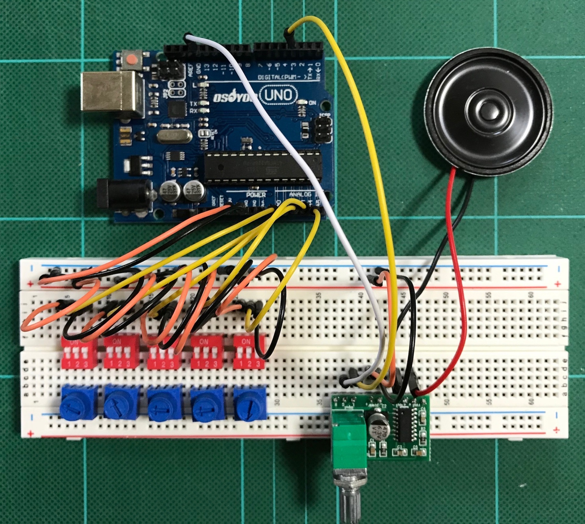
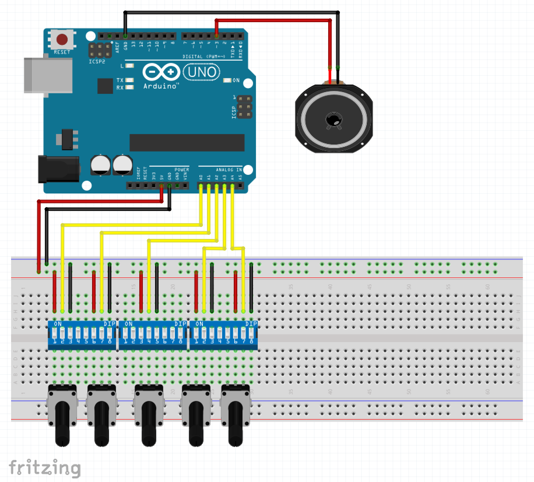
�iFritzing�ɂR�Ƀf�B�b�v�X�C�b�`���Ȃ������̂łW�ɂő�p�j
�i�Q�j�X�P�b�`
�X�P�b�`��auduino_v5�Ɠ���
�i�R�j���s
�ł͎��s���ăf�B�b�v�X�C�b�`���������Ă݂܂�
�ꉞ�ł��Ă��邩��
�f�B�b�v�X�C�b�`���g��Ȃ��Ă��A�܂݂��O���O�����������Ƃœ����悤�ȉ����o�����ł����A�f�B�b�v�X�C�b�`�����������u�Ԃɉ����ω�����̂͂܂݂Ƃ͈�����ʔ���������܂�
����͂����܂�
�ł͂܂��`
| �V�i���i |
| Raspberry Pi3 Model B �{�[�h���P�[�X�Z�b�g (Element14��, Clear)-Physical Computing Lab �V�i���i |
| Arduino���͂��߂悤 ��3�� (Make:PROJECTS) �V�i���i |
| �V�i���i |
| �V�i���i |
| Arduino �G���g���[�L�b�g(Uno�Łj- Physical Computing Lab �V�i���i |
| �^�~�� �y�����H��V���[�Y No.216 3ch RC���{�b�g����Z�b�g 70216 �V�i���i |
| �G���L�b�g ���������{�b�g�A�[�� MR-9105 �V�i���i |
| �G���L�b�g �o�g���^�C�^��2 MR-9101R �V�i���i |
| �V�i���i |
| �^�~�� �y�����H��V���[�Y No.211 �A�[���N���[���[�H��Z�b�g 70211 �V�i���i |
| �^�~�� �y�����H��V���[�Y No.97 �c�C�����[�^�[�M���[�{�b�N�X (70097) �V�i���i |
| �^�~�� �y�����H��V���[�Y No.106 4�`�����l���E�����R���{�b�N�X (70106) �V�i���i |
2018�N06��19��
�y�ԊO�҂Q�zAuduino_v5 / �~���g��
�p�[�c�čl
�O���A�u���b�h�{�[�h���auduino_v5��g��ʼn����o����
�����ALTOIDS���ɑg�ݍ��݂������ǁE�E�E

9v�d�r���g�����Ƃ���ƁE�E�EALTOIDS�ʂ̑傫�����E�E�E����͑S���͓���Ȃ���E�E���u�����Ă݂��

�z�����l����Ƃ�����Ɠ��肻���ɂȂ��̂ŁA�������p�[�c��ύX���邱�Ƃɂ��܂���
�P�[�X��傫������̂���ԊȒP���Ƃ������Ƃɂ͋C�����Ȃ����Ƃɂ��܂�
�i�p�[�c�ύX�j
1. ALTOIDS���͉��H�����₷���悤�����n�̂�����
2. Arduino UNO�͏�����Arduino NANO��
3. �|�e���V�����[�^�[�����^�̂�����
4. 9v�d�r�͏�����12v�d�r��
5. 8�� 0.5W �X�s�[�J�[�����^��8�� 1W �X�s�[�J�[��
6. 4�ɃI�[�f�B�I�W���b�N�����ς݊�������������Œ�p�l�W�������Ă���5�s�� �X�e���I�I�[�f�B�I�W���b�N��
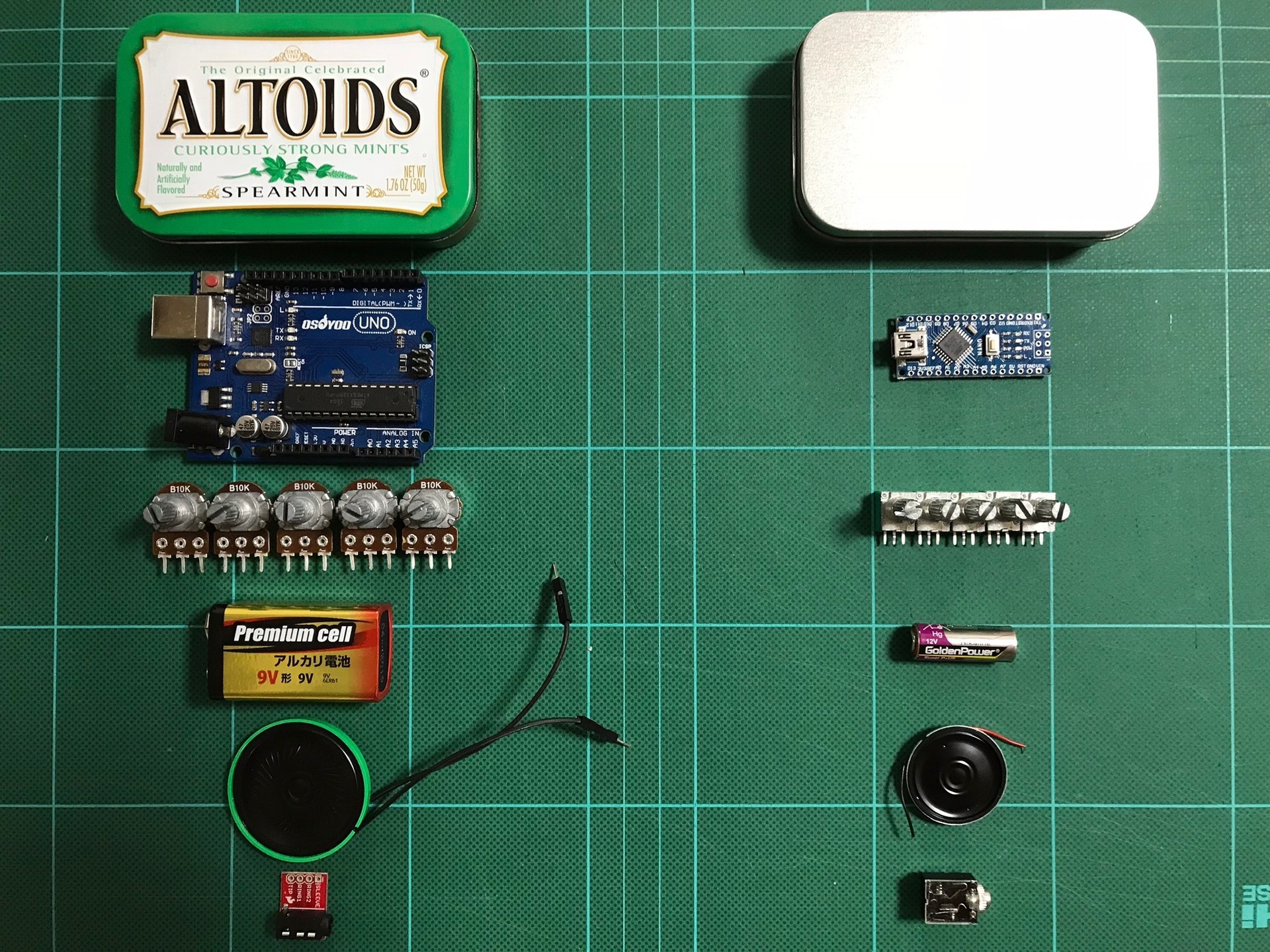
�ύX�����p�[�c�ʼn��u�����Ă݂܂���

����ł�����͂�
����
��������̂���s���Ă�̂őS�̗̂�����Ɏ�����
�i�P�j�i���s�j�z������
�͂��ߊW��̌^�̃~���g�ʂɔz�����ō�������lj��W�̊J���߂�������f���A�V���[�g����Arduino nano����ꂽ�i���j
�i�Q�j�i�����j���j�o�[�T�����
�z��������߂āA�ł��邾�����j�o�[�T����ɍڂ��A�W�̊J���߂����炷���߂ɓd���X�C�b�`��LED������
�i�P�j�z�����iAuduino_v5_1st�j�i���s�j
ALTOIDS�T�C�Y�ʂ̌������Ɣz���̔��c�t���܂ł����đg�ݗ��ĂāE�E�E
�W��߂ĉ��o�������āE�E�E�Ȃ��q�����������Ȃ��āE�E�E�z�����O��ĂāE�E�E���o�������āE�E�E�W��߂āE�E�E�������Ȃ��Ȃ��āE�E�E�z������ĂāE�E�E������蒼���āE�E�E�W�����ĉ����o�Ȃ��ĉ����o�āE�E�E����H���Ǝv������Arduino NANO���������Ȃ��Ȃ��āE�E�E�_���������
Arduino NANO�������Ă��܂��܂����i�ɍ��j
���C���[�̑I����������ȁE�E�Eorz
���̕��@�͓���̂ŐV������蒼���܂�
�i�Q�j���j�o�[�T����iAuduino_v5_2nd�j
Auduino_v5_1st����̉��P��
�i���_�Ɖ��P�_�j
�@ �����X�y�[�X�ł̔z�����ƊW�̊J���߂ŃP�[�u���ɃX�g���X���������ĐڐG�s�ǁE�f���E�V���[�g����nano�������Ă��܂���
�@⇨ �ł��邾��������^�C�v�ɂ���
�A �|�e���V�����[�^�[�܂݊Ԃ̋������������쐫����������
�@⇨ �܂݈ʒu�Ԋu���ł��邾���L�߂ɂƂ�
�B ���ԊW�̊J�����Ŕz���ɃX�g���X��������
�@⇨ �W�����O����^�C�v�ɂ��ĊW�̊J�����Ɏ��R�x����������
�C �X�s�[�J�[���̃f�U�C�������܂������������ʓ|
�@⇨ �X�s�[�J�[���̃f�U�C����ς���
�D �W��߂�Ɠd����ON/OFF��m�F���ł��Ȃ�
�@⇨ �d���X�C�b�`��LED�C���W�P�[�^�[������
�Ƃ��������Ńp�[�c�����܂���
���
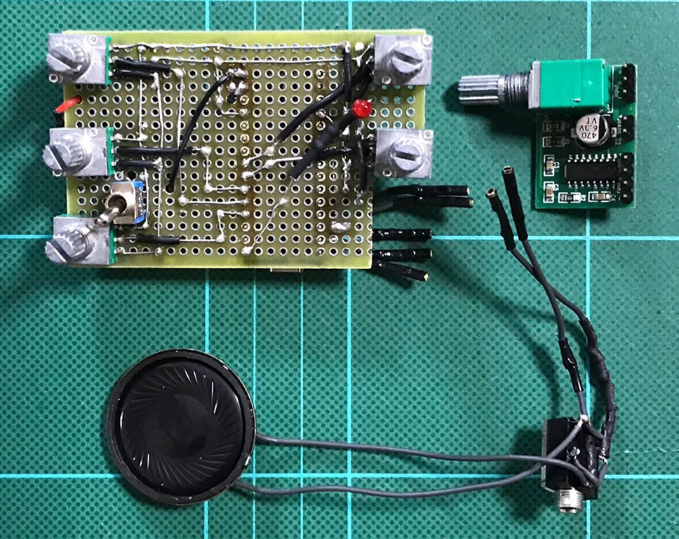
����
�~���g�ʂɓ����O�Ɉ�x�e�X�g���Ă݂�ƃX�s�[�J�[�ł͋C�ɂȂ�Ȃ������m�C�Y���C���z�����ƋC�ɂȂ��āA�{�����[�����ŏ��ɂ���Ɓu�V�[�v���ĉ��ƒႢ�u���[�v�݂����ȉ������������̂ŏo�͂�47���̒�R�����܂��ė}����
�m�C�Y�����S�ɗ}���悤�Ƃ���ƃX�s�[�J�[����̏o�͂������邵�A�Ⴗ����ƃm�C�Y�����ɂȂ�̂ł��̊Ԃ�47���ɂ��܂���
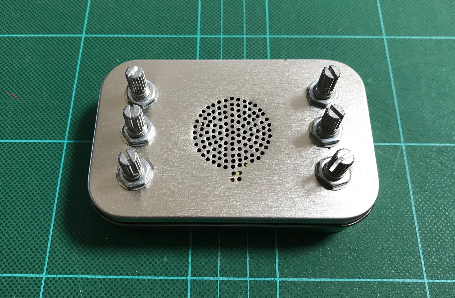
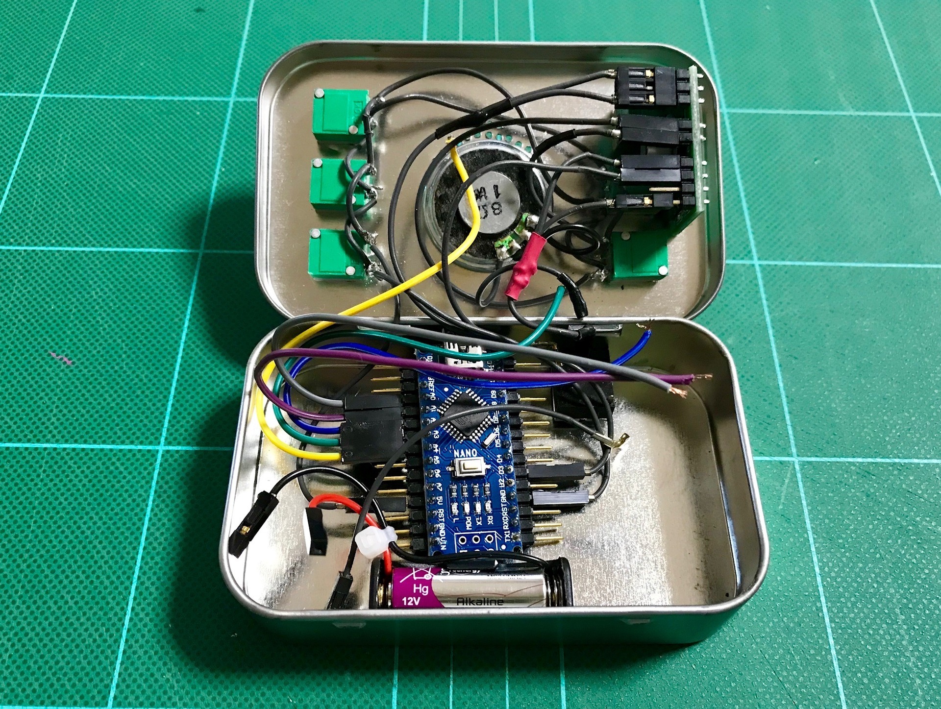
�g�ݗ��ĂƓ���e�X�g
�~���g�ʂɑg�ݓ���܂�
�ł��܂����I
����
����Ŋ����ł�������
�ł͂܂��`
| �V�i���i |
| Raspberry Pi3 Model B �{�[�h���P�[�X�Z�b�g (Element14��, Clear)-Physical Computing Lab �V�i���i |
| Arduino���͂��߂悤 ��3�� (Make:PROJECTS) �V�i���i |
| �V�i���i |
| �V�i���i |
| Arduino �G���g���[�L�b�g(Uno�Łj- Physical Computing Lab �V�i���i |
| �^�~�� �y�����H��V���[�Y No.216 3ch RC���{�b�g����Z�b�g 70216 �V�i���i |
| �G���L�b�g ���������{�b�g�A�[�� MR-9105 �V�i���i |
| �G���L�b�g �o�g���^�C�^��2 MR-9101R �V�i���i |
| �V�i���i |
| �^�~�� �y�����H��V���[�Y No.211 �A�[���N���[���[�H��Z�b�g 70211 �V�i���i |
| �^�~�� �y�����H��V���[�Y No.97 �c�C�����[�^�[�M���[�{�b�N�X (70097) �V�i���i |
| �^�~�� �y�����H��V���[�Y No.106 4�`�����l���E�����R���{�b�N�X (70106) �V�i���i |
2018�N06��12��
�y�ԊO�҂P�zAuduino_v5 / �u���b�h�{�[�h
Auduino���āH
���{�b�g�̂��߂�Arduino�̂��ƂׂĂ���Ƃ���"Auduino"�Ƃ����̂���������
Auduino��Arduino���g�����V���Z�T�C�U�[�̂悤�Ȃ��̂̂悤
���{�b�g���ƒ��ڊW�Ȃ����NJ�蓹�͊y����
�Ƃ����킯���ԊO��
����́A��6��u�V���v���Ȃ̂ɏo�����������V���Z�T�C�U - Auduino����v���Q�l�ɁuAuduino_v5�v�����܂�

���̋L���́E�E�E(2009�N 7�� 16��)�̂��̂Ȃ�ł����ˁE�E�E���\�O�ł��ˁE�E�E�m�����
�ł́A����Ă݂܂�
�u���b�h�{�[�h��Auduino
�i�P�j�z��
�u���b�h�{�[�h���g���đg��ł݂܂�
�i�ޗ��j
�@�@1. Arduino UNO �i�݊��i�jx1
�@�@2. Arduino UNO�t����USB�P�[�u�� x1
�@�@3. B10K�|�e���V�����[�^�[ x5
�@�@4. 0.5W�X�s�[�J�[ x1
�@�@5. �u���b�h�{�[�h x1
�@�@6. �W�����p���C���[ x�K�v��
����Ȃɕ��G���ᖳ���̂Ńu���b�h�{�[�h����Ȃ���ł����E�E�E

�ꉞ�ł��܂���
�ʐ^���Ƃ킩��ɂ����̂�Fritzing���u����
�i�Q�j�X�P�b�`
�X�P�b�`����6��u�V���v���Ȃ̂ɏo�����������V���Z�T�C�U - Auduino����v�̋L�����ɏЉ��Ă���tinker.it �̃��X�g����auduino_v5.pde���_�E�����[�h����Auduino IDE�ŊJ���܂�
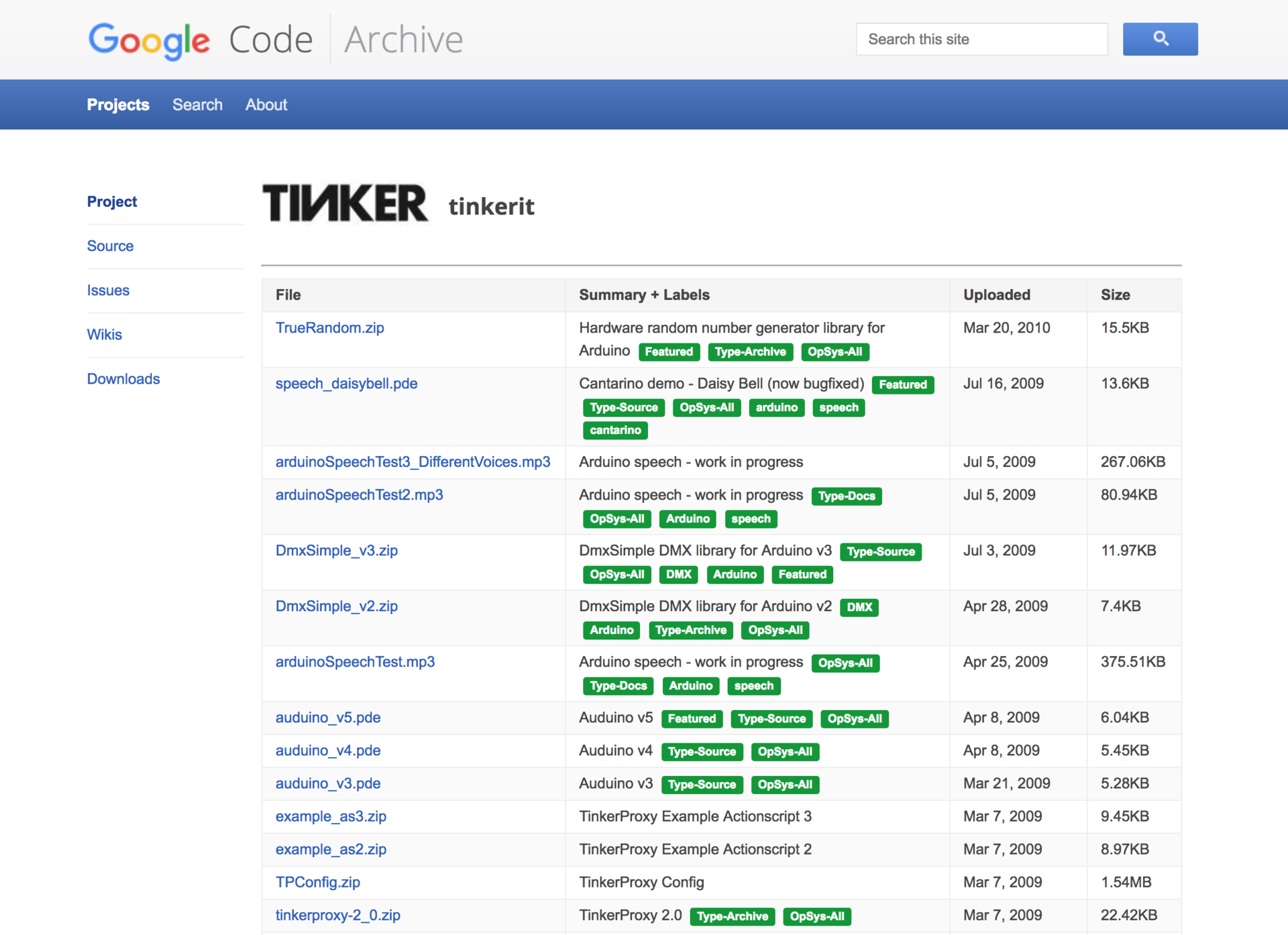
auduino_v5
�\�\�\�\�\�\�\�\�\�\(auduino_v5)�\�\�\�\�\�\�\�\�\�\
// Auduino, the Lo-Fi granular synthesiser
//
// by Peter Knight, Tinker.it http://tinker.it
//
// Help: http://code.google.com/p/tinkerit/wiki/Auduino
// More help: http://groups.google.com/group/auduino
//
// Analog in 0: Grain 1 pitch
// Analog in 1: Grain 2 decay
// Analog in 2: Grain 1 decay
// Analog in 3: Grain 2 pitch
// Analog in 4: Grain repetition frequency
//
// Digital 3: Audio out (Digital 11 on ATmega8)
//
// Changelog:
// 19 Nov 2008: Added support for ATmega8 boards
// 21 Mar 2009: Added support for ATmega328 boards
// 7 Apr 2009: Fixed interrupt vector for ATmega328 boards
// 8 Apr 2009: Added support for ATmega1280 boards (Arduino Mega)
#include
#include
uint16_t syncPhaseAcc;
uint16_t syncPhaseInc;
uint16_t grainPhaseAcc;
uint16_t grainPhaseInc;
uint16_t grainAmp;
uint8_t grainDecay;
uint16_t grain2PhaseAcc;
uint16_t grain2PhaseInc;
uint16_t grain2Amp;
uint8_t grain2Decay;
// Map Analogue channels
#define SYNC_CONTROL (4)
#define GRAIN_FREQ_CONTROL (0)
#define GRAIN_DECAY_CONTROL (2)
#define GRAIN2_FREQ_CONTROL (3)
#define GRAIN2_DECAY_CONTROL (1)
// Changing these will also requires rewriting audioOn()
#if defined(__AVR_ATmega8__)
//
// On old ATmega8 boards.
// Output is on pin 11
//
#define LED_PIN 13
#define LED_PORT PORTB
#define LED_BIT 5
#define PWM_PIN 11
#define PWM_VALUE OCR2
#define PWM_INTERRUPT TIMER2_OVF_vect
#elif defined(__AVR_ATmega1280__)
//
// On the Arduino Mega
// Output is on pin 3
//
#define LED_PIN 13
#define LED_PORT PORTB
#define LED_BIT 7
#define PWM_PIN 3
#define PWM_VALUE OCR3C
#define PWM_INTERRUPT TIMER3_OVF_vect
#else
//
// For modern ATmega168 and ATmega328 boards
// Output is on pin 3
//
#define PWM_PIN 3
#define PWM_VALUE OCR2B
#define LED_PIN 13
#define LED_PORT PORTB
#define LED_BIT 5
#define PWM_INTERRUPT TIMER2_OVF_vect
#endif
// Smooth logarithmic mapping
//
uint16_t antilogTable[] = {
64830,64132,63441,62757,62081,61413,60751,60097,59449,58809,58176,57549,56929,56316,55709,55109,
54515,53928,53347,52773,52204,51642,51085,50535,49991,49452,48920,48393,47871,47356,46846,46341,
45842,45348,44859,44376,43898,43425,42958,42495,42037,41584,41136,40693,40255,39821,39392,38968,
38548,38133,37722,37316,36914,36516,36123,35734,35349,34968,34591,34219,33850,33486,33125,32768
};
uint16_t mapPhaseInc(uint16_t input) {
return (antilogTable[input & 0x3f]) >> (input >> 6);
}
// Stepped chromatic mapping
//
uint16_t midiTable[] = {
17,18,19,20,22,23,24,26,27,29,31,32,34,36,38,41,43,46,48,51,54,58,61,65,69,73,
77,82,86,92,97,103,109,115,122,129,137,145,154,163,173,183,194,206,218,231,
244,259,274,291,308,326,346,366,388,411,435,461,489,518,549,581,616,652,691,
732,776,822,871,923,978,1036,1097,1163,1232,1305,1383,1465,1552,1644,1742,
1845,1955,2071,2195,2325,2463,2610,2765,2930,3104,3288,3484,3691,3910,4143,
4389,4650,4927,5220,5530,5859,6207,6577,6968,7382,7821,8286,8779,9301,9854,
10440,11060,11718,12415,13153,13935,14764,15642,16572,17557,18601,19708,20879,
22121,23436,24830,26306
};
uint16_t mapMidi(uint16_t input) {
return (midiTable[(1023-input) >> 3]);
}
// Stepped Pentatonic mapping
//
uint16_t pentatonicTable[54] = {
0,19,22,26,29,32,38,43,51,58,65,77,86,103,115,129,154,173,206,231,259,308,346,
411,461,518,616,691,822,923,1036,1232,1383,1644,1845,2071,2463,2765,3288,
3691,4143,4927,5530,6577,7382,8286,9854,11060,13153,14764,16572,19708,22121,26306
};
uint16_t mapPentatonic(uint16_t input) {
uint8_t value = (1023-input) / (1024/53);
return (pentatonicTable[value]);
}
void audioOn() {
#if defined(__AVR_ATmega8__)
// ATmega8 has different registers
TCCR2 = _BV(WGM20) | _BV(COM21) | _BV(CS20);
TIMSK = _BV(TOIE2);
#elif defined(__AVR_ATmega1280__)
TCCR3A = _BV(COM3C1) | _BV(WGM30);
TCCR3B = _BV(CS30);
TIMSK3 = _BV(TOIE3);
#else
// Set up PWM to 31.25kHz, phase accurate
TCCR2A = _BV(COM2B1) | _BV(WGM20);
TCCR2B = _BV(CS20);
TIMSK2 = _BV(TOIE2);
#endif
}
void setup() {
pinMode(PWM_PIN,OUTPUT);
audioOn();
pinMode(LED_PIN,OUTPUT);
}
void loop() {
// The loop is pretty simple - it just updates the parameters for the oscillators.
//
// Avoid using any functions that make extensive use of interrupts, or turn interrupts off.
// They will cause clicks and poops in the audio.
// Smooth frequency mapping
//syncPhaseInc = mapPhaseInc(analogRead(SYNC_CONTROL)) / 4;
// Stepped mapping to MIDI notes: C, Db, D, Eb, E, F...
//syncPhaseInc = mapMidi(analogRead(SYNC_CONTROL));
// Stepped pentatonic mapping: D, E, G, A, B
syncPhaseInc = mapPentatonic(analogRead(SYNC_CONTROL));
grainPhaseInc = mapPhaseInc(analogRead(GRAIN_FREQ_CONTROL)) / 2;
grainDecay = analogRead(GRAIN_DECAY_CONTROL) / 8;
grain2PhaseInc = mapPhaseInc(analogRead(GRAIN2_FREQ_CONTROL)) / 2;
grain2Decay = analogRead(GRAIN2_DECAY_CONTROL) / 4;
}
SIGNAL(PWM_INTERRUPT)
{
uint8_t value;
uint16_t output;
syncPhaseAcc += syncPhaseInc;
if (syncPhaseAcc < syncPhaseInc) {
// Time to start the next grain
grainPhaseAcc = 0;
grainAmp = 0x7fff;
grain2PhaseAcc = 0;
grain2Amp = 0x7fff;
LED_PORT ^= 1 << LED_BIT; // Faster than using digitalWrite
}
// Increment the phase of the grain oscillators
grainPhaseAcc += grainPhaseInc;
grain2PhaseAcc += grain2PhaseInc;
// Convert phase into a triangle wave
value = (grainPhaseAcc >> 7) & 0xff;
if (grainPhaseAcc & 0x8000) value = ~value;
// Multiply by current grain amplitude to get sample
output = value * (grainAmp >> 8);
// Repeat for second grain
value = (grain2PhaseAcc >> 7) & 0xff;
if (grain2PhaseAcc & 0x8000) value = ~value;
output += value * (grain2Amp >> 8);
// Make the grain amplitudes decay by a factor every sample (exponential decay)
grainAmp -= (grainAmp >> 8) * grainDecay;
grain2Amp -= (grain2Amp >> 8) * grain2Decay;
// Scale output to the available range, clipping if necessary
output >>= 9;
if (output > 255) output = 255;
// Output to PWM (this is faster than using analogWrite)
PWM_VALUE = output;
}
�\�\�\�\�\�\�\�\�\�\�\�\�\�\�\�\�\�\�\�\�\�\�\�\�\�\�\
�i�R�j���s
�i�Q�j�̃X�P�b�`��Arduino�ɏ�������Ŏ��s���܂�
���߂͏����ȃr�[�v�������������Ȃ��āA�Ȃ��s�������Ȃ��Ċ�����������ł����A�m�u��F�X�������Ă݂�Ƃ���Ȃ�ɉ�����������悤�ɂȂ�܂���
������Ɗy�����Ă��낢�낢�����ėV��ł��܂���
�ł��E�E�E�����������Ƃ������E�E�E���������̒��ɂ��������ɉ��̕ω�������Ƃ������E�E�E���������Ƃ��Ă���悤�ȁE�E�E
�����Ƒ傫�ȃX�s�[�J�[�Ɍq���Ƃ��C���z���Œ����������ǂ����ȁH
�Ƃ����킯�ŁA4�ɃI�[�f�B�I�W���b�N�����ς݊���ɂȂ��ŃC���z���Œ����Ă݂܂�

4�ɃI�[�f�B�I�W���b�N�����ς݊��
�C���z������o�Ă��鉹�����ł��X�s�[�J�[���傫���悤�ȁE�E�E
�r���C���z���̍��E�̂Ȃ��ς��̕��@���m���߂��肵�Ă܂�
�����������Ȃ��Ƃ���ł͎��ɃC���z�������Ē����Ă܂�
�C���z�������Œ�������A�����ɂ����炢�̑剹�ʂɂȂ������ǁA���̌X���͕ς�炸�A�t�ɃQ�C�����傫������Ǝ��ɗǂ����������Œ����ɂ���
�S�����r�r���m�C�Y�������Ă���悤�ȁE�E�E
����̓A���v�Ɍq���Ń{�����[�����߂ł��Ȃ��ƃ_���Ȃ�E�E�E�I�[�f�B�I�W���b�N�o�R�ŃA���v�t���X�s�[�J�[�Ɍq�����������̂��ȁE�E�E�����^�тł���Ƃ������E�E�E
�Ȃ����̂Ȃ����Ȃ����ăO�O���Ă�Amazon���{�����[���m�u�̂������^�I�[�f�B�I�A���v�{�[�h���������̂łȂ��ł݂�
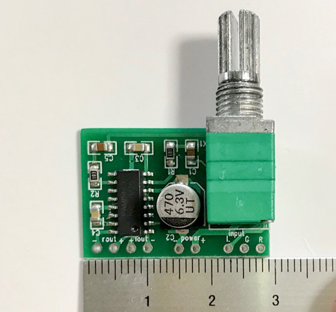
���^�I�[�f�B�I�A���v�{�[�h
���^�I�[�f�B�I�A���v�{�[�h�̃X���[�z�[���ɒ��ڃW�����p�[�����Ȃ��Őڑ����Ă���̂łƂ���ǂ���ڐG�������ĉ������ł܂��E�E�E
���ʂ͂܂��A������Ȃ��ł��傤��
�����ȉ��̕ω����E���₷���Ȃ����悤�ȋC�����܂�
���ꂭ�炢�̍\���ň�x�P�[�X�ɑg�ݍ���ł݂悤�Ǝv���܂�
�ł͂܂��`
| �V�i���i |
| Raspberry Pi3 Model B �{�[�h���P�[�X�Z�b�g (Element14��, Clear)-Physical Computing Lab �V�i���i |
| Arduino���͂��߂悤 ��3�� (Make:PROJECTS) �V�i���i |
| �V�i���i |
| �V�i���i |
| Arduino �G���g���[�L�b�g(Uno�Łj- Physical Computing Lab �V�i���i |
| �^�~�� �y�����H��V���[�Y No.216 3ch RC���{�b�g����Z�b�g 70216 �V�i���i |
| �G���L�b�g ���������{�b�g�A�[�� MR-9105 �V�i���i |
| �G���L�b�g �o�g���^�C�^��2 MR-9101R �V�i���i |
| �V�i���i |
| �^�~�� �y�����H��V���[�Y No.211 �A�[���N���[���[�H��Z�b�g 70211 �V�i���i |
| �^�~�� �y�����H��V���[�Y No.97 �c�C�����[�^�[�M���[�{�b�N�X (70097) �V�i���i |
| �^�~�� �y�����H��V���[�Y No.106 4�`�����l���E�����R���{�b�N�X (70106) �V�i���i |
2016�N09��24��
A6�F�T ���x�ȓ��͂Əo�́F�A�i���O���o�� LED�����v�쐬
�A�i���O����+PWM�o�� LED�����v�쐬
�O�X���A�O���A���wArduino���͂��߂悤 ��3�Łx��4�̓X�P�b�`���� �ł�LED���f�W�^�����o�͐��䂵�܂���
��T�� ���x�ȓ��͂Əo���ł̓A�i���O���o��LED�����v�����悤�ł�
| Arduino���͂��߂悤 ��3�� (Make:PROJECTS) �V�i���i |
�@�@�y�[�W�@���s���e�@�@�@�@�@�@�@�@�@�@�@�@�@�@�@ �@�@�X�P�b�`
�@�@051�@�@������薾�ł���LED�@�@�@�@�@�@�@�@�@�@�@�@E.5-1
�@�@053�@�@�{�^����LED�̖��邳�߂���@�@�@�@�@�@�@E.5-2
�@�@057�@�@�A�i���O���͂ɉ�����LED�_�Ń��[�g���ω��@�@E.5-3
�@�@057�@�@�A�i���O���͂ɉ�����LED�̖��邳��ς���@�@E.5-4
�@�@059�@�@�A�i���O���̓s���̒l���R���s���[�^�֑���@�@ E.5-5
��T���̗���͈ȉ��̂悤�ɂȂ��Ă��܂�
�@�@�@�@�@�@�@�@E.5-1�@�A�i���O�o��
�@�@�@�@�@�@�@�@E.5-2�@�f�W�^�����́A�A�i���O�o��
�@�@�@�@�@�@�@�@E.5-3�@�A�i���O���́A�f�W�^���o��
�@�@�@�@�@�@�@�@E.5-4�@�A�i���O���́A�A�i���O�o��
�@�@�@�@�@�@�@�@E.5-5�@�V���A���ʐM�@
051 ������薾�ł���LED�FE.5-1
�i�P�j��H�v
�ړI�F�@PWM�o�͂�LED��������薾�ł����܂�
�@�@�@�@�i�A�i���O�o�́j
�ޗ��F�@Mac (Arduino IDE), Arduino UNO�{�[�h, LED x1,
�@�@�@�@�u���b�h�{�[�h, �W�����v���C��, ��R��i1K���j
��H�F�@��H5-1

�����̒�R��220���ȏ��p���邱�ƂɂȂ��Ă܂����A�wArduino���͂��߂悤 �݊��L�b�g�x�ł�200���̎��ɑ傫�����̂�1K���ł���

| �V�i���i |
�i�Q�j�v���O���~���O
���X�P�b�` �́A�����łŌ��J����Ă���X�P�b�`�f�[�^��p���܂�
�i�ȉ�Example 5-5�܂œ��l�j
E5_1_Fade
�\�\�\�\�\�\�\�\�\�\(Example 5-1)�\�\�\�\�\�\�\�\�\�\
// Fade an LED in and out, like on a sleeping Apple computer
const int LED = 9; // the pin for the LED
int i = 0; // We'll use this to count up and down
void setup() {
pinMode(LED, OUTPUT); // tell Arduino LED is an output
}
void loop(){
for (i = 0; i < 255; i++) { // loop from 0 to 254 (fade in)
analogWrite(LED, i); // set the LED brightness
delay(10); // Wait 10ms because analogWrite
// is instantaneous and we would
// not see any change
}
for (i = 255; i > 0; i--) { // loop from 255 to 1 (fade out)
analogWrite(LED, i); // set the LED brightness
delay(10); // Wait 10ms
}
}
�\�\�\�\�\�\�\�\�\�\�\�\�\�\�\�\�\�\�\�\�\�\�\�\�\�\�\
�i�R�j���s
���FLED��������薾�邭�Ȃ�����Â��Ȃ����肵�܂�
�X�P�b�`��"like on a sleeping Apple computer"�Ƃ���܂����A���傤��MacBook�̃X���[�v�C���W�P�[�^���C�g (SIL)�̂悤�ȓ��������܂�
053 �{�^����LED�̖��邳�߂���FE.5-2
���́A��H5-1�Ƀv�b�V���{�^����lj����A�{�^���̉�������LED�̓_���▾�邳�߂��܂�
�i�P�j��H�v
�ړI�F�@�u�b�V���{�^���̉�������LED�̓_���E�����Ɩ��邳�𐧌䂷��
�@�@�@�@�i�f�W�^�����́A�A�i���O�o�́j
�ޗ��F�@Mac (Arduino IDE), Arduino UNO�{�[�h, LED x1,
�@�@�@�@�u���b�h�{�[�h, �W�����v���C��, ��R��i1K���j,
�@�@�@�@��R��i10K���j, �v�b�V���{�^���i�^�N�g�X�C�b�`�j
��H�F�@��H5-2

�i�Q�j�v���O���~���O
�@�{�^���������Ă����ɗ���������LED�̓_���A�������s���A
�A�{�^��������������i500 ms�ȏ�j��LED�̖��邳���ω����A���������_�̖��邳�ŌŒ肷��悤�ɂ��܂�
E5_2_ButtonHold
�\�\�\�\�\�\�\�\�\�\(Example 5-2)�\�\�\�\�\�\�\�\�\�\
// Sketch to change the brightness as you hold the button
const int LED = 9; // the pin for the LED
const int BUTTON = 7; // input pin of the pushbutton
int val = 0; // stores the state of the input pin
int old_val = 0; // stores the previous value of "val"
int state = 0; // 0 = LED off while 1 = LED on
int brightness = 128; // Stores the brightness value
unsigned long startTime = 0; // when did we begin pressing?
void setup() {
pinMode(LED, OUTPUT); // tell Arduino LED is an output
pinMode(BUTTON, INPUT); // and BUTTON is an input
}
void loop() {
val = digitalRead(BUTTON); // read input value and store it
// yum, fresh
// check if there was a transition
if ((val == HIGH) && (old_val == LOW)) {
state = 1 - state; // change the state from off to on
// or vice-versa
startTime = millis(); // millis() is the Arduino clock
// it returns how many milliseconds
// have passed since the board has
// been reset.
// (this line remembers when the button
// was last pressed)
delay(10);
}
// check whether the button is being held down
if ((val == HIGH) && (old_val == HIGH)) {
// If the button is held for more than 500 ms.
if (state == 1 && (millis() - startTime) > 500) {
brightness++; // increment brightness by 1
delay(10); // delay to avoid brightness going
// up too fast
if (brightness > 255) { // 255 is the max brightness
brightness = 0; // if we go over 255
// let's go back to 0
}
}
}
old_val = val; // val is now old, let's store it
if (state == 1) {
analogWrite(LED, brightness); // turn LED ON at the
// current brightness level
} else {
analogWrite(LED, 0); // turn LED OFF
}
}
�\�\�\�\�\�\�\�\�\�\�\�\�\�\�\�\�\�\�\�\�\�\�\�\�\�\�\
�i�R�j���s
�f�����{�^����������LED���_������������肵�܂�
�����������LED��������薾�邭�Ȃ�����Â��Ȃ����肵�A�{�^������w�𗣂������̖��邳�ŌŒ肳��܂�
057 �A�i���O���͂ɉ�����LED�_�Ń��[�g���ω��FE.5-3
�����ł����Z���T��p���ăA�i���O���͂��s���A���̒l�ɉ�����LED�̓_�Ń��[�g�𐧌䂵�܂�
�i�P�j��H�v
�ړI�F�@���Z���T��LED�̓_�Ń��[�g�𐧌䂷��
�@�@�@�@�i�A�i���O���́A�f�W�^���o�́j
�ޗ��F�@Mac (Arduino IDE), Arduino UNO�{�[�h, LED x1,
�@�@�@�@�u���b�h�{�[�h, �W�����v���C��, ��R��i10K���j,
�@�@�@�@���Z���T
��H�F�@��H5-3

�i�Q�j�v���O���~���O
E5_3_BlinkRate
�\�\�\�\�\�\�\�\�\�\(Example 5-3)�\�\�\�\�\�\�\�\�\�\
// Blink LED at a rate specified by the value of the analogue input
const int LED = 13; // the pin for the LED
int val = 0; // variable used to store the value
// coming from the sensor
void setup() {
pinMode(LED, OUTPUT); // LED is as an OUTPUT
// Note: Analogue pins are
// automatically set as inputs
}
void loop() {
val = analogRead(0); // read the value from
// the sensor
digitalWrite(LED, HIGH); // turn the LED on
delay(val); // stop the program for
// some time
digitalWrite(LED, LOW); // turn the LED off
delay(val); // stop the program for
// some time
}
�\�\�\�\�\�\�\�\�\�\�\�\�\�\�\�\�\�\�\�\�\�\�\�\�\�\�\
�i�R�j���s
���Z���T�ɓ�������̗ʂɂ����13�ԃs��LED�̓_�ŃX�s�[�h���ω����܂�
�i����͍Ō�ɂ܂Ƃ߂Ď����܂��FExample 5-3�j
057 �A�i���O���͂ɉ�����LED�̖��邳��ς���FE.5-4
�����āAPWM�o�́i�A�i���O�o�́j��9�ԃs����LED��ڑ����A���Z���T�̒l�ɉ�����LED�̖��邳�𐧌䂵�܂�
�i�P�j��H�v
�ړI�F�@���Z���T��LED�̖��邳�𐧌䂷��
�@�@�@�@�i�A�i���O���́A�A�i���O�o�́j
�ޗ��F�@Mac (Arduino IDE), Arduino UNO�{�[�h, LED x1,
�@�@�@�@�u���b�h�{�[�h, �W�����v���C��, ��R��i10K���j,
�@�@�@�@��R��i1K���j, ���Z���T
��H�F�@��H5-4

�i�Q�j�v���O���~���O
E5_4_LEDBrightness
�\�\�\�\�\�\�\�\�\�\(Example 5-4)�\�\�\�\�\�\�\�\�\�\
// Set the LED to a brightness specified by the value of the analogue input
const int LED = 9; // the pin for the LED
int val = 0; // variable used to store the value
// coming from the sensor
void setup() {
pinMode(LED, OUTPUT); // LED is as an OUTPUT
// Note: Analogue pins are
// automatically set as inputs
}
void loop() {
val = analogRead(0); // read the value from
// the sensor
analogWrite(LED, val/4); // turn the LED on at
// the brightness set
// by the sensor
delay(10); // stop the program for
// some time
}
�\�\�\�\�\�\�\�\�\�\�\�\�\�\�\�\�\�\�\�\�\�\�\�\�\�\�\
�i�R�j���s
���Z���T�ɓ�������̗ʂɂ����9�ԃs��LED�̖��邳���ω����܂�
059 �A�i���O���̓s���̒l���R���s���[�^�֑���FE.5-5
Example 5-4�ő�T�̖͂ړI�ł���A�i���O���o��LED�����v���ł��܂���
��������p����Ύ��肪�Â��Ȃ�ɏ]���Ė��邭�Ȃ郂�j�^�[��L�[�{�[�h�o�b�N���C�g�������ł�����
�Ō�Ɍ��Z���T���g���ăA�i���O���͂̒l��ǂݎ��Serial monitor�̎g�����i�V���A���ʐM�j���w�т܂�
�i�P�j��H�v
��H5-4�ɓ���
�i�Q�j�v���O���~���O
E5_5_Serial
�\�\�\�\�\�\�\�\�\�\(Example 5-5)�\�\�\�\�\�\�\�\�\�\
// Send the computer the values read from analogue input 0
const int SENSOR = 0; // select the input pin for the
// sensor resistor
int val = 0; // variable to store the value coming
// from the sensor
void setup() {
Serial.begin(9600); // open the serial port to send
// data back to the computer at
// 9600 bits per second
}
void loop() {
val = analogRead(SENSOR); // read the value from
// the sensor
Serial.println(val); // print the value to
// the serial port
delay(100); // wait 100ms between
// each send
}
�\�\�\�\�\�\�\�\�\�\�\�\�\�\�\�\�\�\�\�\�\�\�\�\�\�\�\
�i�R�j���s
Arduino�{�[�h�ɃX�P�b�`���������݁AArduino IDE��Serial monitor�{�^���������ƌ��Z���T����̒l��\�����܂�
Example 5-1�`5-5�̓���܂Ƃ�
�Ō�ɍ����Example 5-1�`5-5�̎����̓���������܂�
YouTube�@�@
�ȏ�ŁA�wArduino���͂��߂悤 ��3�Łx��T���̂������I���܂�
�ł͂܂��`
| �V�i���i |
| Raspberry Pi3 Model B �{�[�h���P�[�X�Z�b�g (Element14��, Clear)-Physical Computing Lab �V�i���i |
| Arduino���͂��߂悤 ��3�� (Make:PROJECTS) �V�i���i |
| �V�i���i |
| �V�i���i |
| Arduino �G���g���[�L�b�g(Uno�Łj- Physical Computing Lab �V�i���i |
| �^�~�� �y�����H��V���[�Y No.216 3ch RC���{�b�g����Z�b�g 70216 �V�i���i |
| �G���L�b�g ���������{�b�g�A�[�� MR-9105 �V�i���i |
| �G���L�b�g �o�g���^�C�^��2 MR-9101R �V�i���i |
| �V�i���i |
| �^�~�� �y�����H��V���[�Y No.211 �A�[���N���[���[�H��Z�b�g 70211 �V�i���i |
| �^�~�� �y�����H��V���[�Y No.97 �c�C�����[�^�[�M���[�{�b�N�X (70097) �V�i���i |
| �^�~�� �y�����H��V���[�Y No.106 4�`�����l���E�����R���{�b�N�X (70106) �V�i���i |
2016�N09��20��
A5�F�S �X�P�b�`����F�f�W�^�����o�� LED�����v�쐬�A
�O��̑����ł�
�@�@�y�[�W�@�@���s���e�@�@�@�@�@�@�@�@�@�@�@�@�@�@�@�@�X�P�b�`
�@�@038�@�@�@�{�^����������Ă���ԁALED��_����@�@E.4-2
�@�@040�@�@�@�{�^�����P���Ɠ_���𑱂���LED�@�@�@E.4-3
�@�@042�@�@�@�{�^�������������̋��������P�@�@�@�@�@�@E.4-4
�@�@043�@�@�@�o�E���V���O�ɑΉ������ŏI�Ł@�@�@�@�@�@E.4-5
038 �{�^����������Ă���ԁALED��_����FE.4-2
Example 4-1�ł�LED���P�b���Ƃɓ_�ł��܂������A
Example 4-2�ł̓{�^���������Ă���Ԃ���LED���_���܂�
�i�P�j��H�v
�ړI�F�@�v�b�V���{�^���i�Z���T�[�j�ɂ��LED�̓_���𐧌䂷��
�ޗ��F�@Mac (Arduino IDE), Arduino UNO�{�[�h, LED x1,
�@�@�@�@�u���b�h�{�[�h, �W�����v���C��, ��R��i10K���j,
�@�@�@�@�v�b�V���{�^���i�^�N�g�X�C�b�`�j
�@�@�@�@
��H�F�@��H4-2

��H4-1�Ƀu�b�V���{�^������p�u���b�h�{�[�h��7�ԃs���ɐڑ����܂�
���̉�H�ɕK�v�ȕ��i�͑S���wArduino���͂��߂悤 �݊��L�b�g UNO R3�Ή��݊��{�[�h�x�ɓ����Ă��܂���
| �V�i���i |
�i�Q�j�v���O���~���O
�X�P�b�`�FExample 4-2
��L�X�P�b�` E.4-1���l�A�����łŌ��J����Ă���X�P�b�`�f�[�^��p���܂��i�ȉ�Example 4-5�܂œ��l�j
E4_2_LED_Button
�\�\�\�\�\�\�\�\�\�\(Example 4-2)�\�\�\�\�\�\�\�\�\�\
// Turn on LED while the button is pressed
const int LED = 13; // the pin for the LED
const int BUTTON = 7; // the input pin where the
// pushbutton is connected
int val = 0; // val will be used to store the state
// of the input pin
void setup() {
pinMode(LED, OUTPUT); // tell Arduino LED is an output
pinMode(BUTTON, INPUT); // and BUTTON is an input
}
void loop(){
val = digitalRead(BUTTON); // read input value and store it
// check whether the input is HIGH (button pressed)
if (val == HIGH) {
digitalWrite(LED, HIGH); // turn LED ON
} else {
digitalWrite(LED, LOW);
}
}
�\�\�\�\�\�\�\�\�\�\�\�\�\�\�\�\�\�\�\�\�\�\�\�\�\�\�\
�i�R�j���s
���ۂɓ������ƁA�{�^���������Ă���Ԃ���LED���_���܂�
40 �{�^�����P���Ɠ_���𑱂���LED�FE.4-3
Example 4-2�̂悤��LED��_�������邽�߂Ƀ{�^�������������Ȃ��Ă͂����Ȃ��̂͑�ςł��̂ŁAExample 4-3�ł̓{�^�����P����LED���_�����A������x�����Ə�������悤�ɂ�����
�i�P�j��H�v
Example 4-2�ɓ���
�i�Q�j�v���O���~���O
�X�P�b�`�FExample 4-3
E4_3_LED_KeepOn
�\�\�\�\�\�\�\�\�\�\(Example 4-3)�\�\�\�\�\�\�\�\�\�\
// Turn on LED when the button is pressed and keep it on after it is released
const int LED = 13; // the pin for the LED
const int BUTTON = 7; // the input pin where the
// pushbutton is connected
int val = 0; // val will be used to store the state
// of the input pin
int state = 0; // 0 = LED off while 1 = LED on
void setup() {
pinMode(LED, OUTPUT); // tell Arduino LED is an output
pinMode(BUTTON, INPUT); // and BUTTON is an input
}
void loop() {
val = digitalRead(BUTTON); // read input value and store it
// check if the input is HIGH (button pressed)
// and change the state
if (val == HIGH) {
state = 1 - state;
}
if (state == 1) {
digitalWrite(LED, HIGH); // turn LED ON
} else {
digitalWrite(LED, LOW);
}
}
�\�\�\�\�\�\�\�\�\�\�\�\�\�\�\�\�\�\�\�\�\�\�\�\�\�\�\
Example 4-2����̕ύX�_���Ԏ��Ŏ����Ă��܂�
�i�R�j���s
�{�^����������LED���_���܂��E�E�E���A���������ɓ_���������邩�͋C������Ƃ������E�E�E�����_���Ȃ悤�ȁE�E�E�����Ă��鎞�Ԉˑ��I�Ȃ悤�ȕs����ȋ��������܂�
����� state = 1 - state;�@�ɂ����
LED�̏�ԁistate�j��1�i�_���j�Ȃ� state = 1 - state(=1)���O�i�����j
LED�̏�ԁistate�j��0�i�����j�Ȃ� state = 1 - state(=0)��1�i�_���j
�Ƃ���LED�̏�Ԃ�ς��܂����A�{�^���������Ă���ق�̂������̊Ԃɂ��̏�ԕω��̓ǂݎ�肪���X�ƕω������R�̌��ʂƂ��Ăǂ��炩�̏�ԂɂȂ�LED����������������肷�邱�ƂɂȂ�܂�
LED�̓_�������R�ɔC����Ƃ����̂��ʔ����̂ł����A�����ł͎��p�I�ɂȂ�悤�ɉ��ǂ��Ă܂�
042 �{�^�������������̋��������P�FE.4-4
Example 4-4�ł�Example 4-3�̕s����X�P�b�`�̉��P����
�i�P�j��H�v
Example 4-2�ɓ���
�i�Q�j�v���O���~���O
�X�P�b�`�FExample 4-4
E4_4_NewImprovedButton
�\�\�\�\�\�\�\�\�\�\(Example 4-4)�\�\�\�\�\�\�\�\�\�\
// New and improved button press formula!
const int LED = 13; // the pin for the LED
const int BUTTON = 7; // the input pin where the
// pushbutton is connected
int val = 0; // val will be used to store the state
// of the input pin
int old_val = 0; // this variable stores the previous
// value of "val"
int state = 0; // 0 = LED off and 1 = LED on
void setup() {
pinMode(LED, OUTPUT); // tell Arduino LED is an output
pinMode(BUTTON, INPUT); // and BUTTON is an input
}
void loop(){
val = digitalRead(BUTTON); // read input value and store it
// yum, fresh
// check if there was a transition
if ((val == HIGH) && (old_val == LOW)){
state = 1 - state;
}
old_val = val; // val is now old, let's store it
if (state == 1) {
digitalWrite(LED, HIGH); // turn LED ON
} else {
digitalWrite(LED, LOW);
}
}
�\�\�\�\�\�\�\�\�\�\�\�\�\�\�\�\�\�\�\�\�\�\�\�\�\�\�\
Example 4-3����̕ύX�_���Ԏ��Ŏ����Ă��܂�
�����ł͉����O�̃{�^���̏�Ԃ�int old_val = 0; �ŕۑ�����
((val == HIGH) && (old_val == LOW))�����������̃{�^���̏��(val)��HIGH������(&&)�����O�̃{�^���̏��(old_val)��LOW�̎� state = 1 - state�Ƃ��邱�ƂŃ{�^���������Ă���Ԃ�state���ω����Ȃ��悤�ɂ��Ă��܂�
�E�E�E�{�^����LED��_������������肷�邾���ł���Ȃɖʓ|���������ƂɂȂ�Ƃ́E�E�E��(^_^;)
�i�R�j���s
�������s���Ă݂��Example 4-3�̎��ƈႢ���킩��܂����(^_^;)
����̓v�b�V���{�^���̋@�B�I�ȐڐG�̖����o�E���X�Ƃ������ۂ̉e���������ŁAdelay��10�`50 ms�قǓ����Ή�������邻���ł�
043 �o�E���V���O�ɑΉ������ŏI�ŁFE.4-5
Example 4-5��Example 4-4�̃o�E���X�̖�����������
�i�P�j��H�v
Example 4-2�ɓ���
�i�Q�j�v���O���~���O
�X�P�b�`�FExample 4-5
E4_5_DebounceWithButton
�\�\�\�\�\�\�\�\�\�\(Example 4-5)�\�\�\�\�\�\�\�\�\�\
// Another new and improved formula for button presses--with simple debouncing!
const int LED = 13; // the pin for the LED
const int BUTTON = 7; // the input pin where the
// pushbutton is connected
int val = 0; // val will be used to store the state
// of the input pin
int old_val = 0; // this variable stores the previous
// value of "val"
int state = 0; // 0 = LED off and 1 = LED on
void setup() {
pinMode(LED, OUTPUT); // tell Arduino LED is an output
pinMode(BUTTON, INPUT); // and BUTTON is an input
}
void loop(){
val = digitalRead(BUTTON); // read input value and store it
// yum, fresh
// check if there was a transition
if ((val == HIGH) && (old_val == LOW)){
state = 1 - state;
delay(10);
}
old_val = val; // val is now old, let's store it
if (state == 1) {
digitalWrite(LED, HIGH); // turn LED ON
} else {
digitalWrite(LED, LOW);
}
}
�\�\�\�\�\�\�\�\�\�\�\�\�\�\�\�\�\�\�\�\�\�\�\�\�\�\�\
Example 4-4����̕ύX�_���Ԏ��Ŏ����Ă��܂�
�����ł� state = 1 - state;�̌�� delay(10);�����Ă��邾���ł�
�i�R�j���s
��H �m���Ƀ}�V�ɂȂ��Ă���悤�Ɏv���܂����A�܂�������ƕs����Ȃ悤�ȁH
����̓v�b�V���X�C�b�`�̖�肩������Ȃ��̂ŁA�Ƃ肠���������
Example 4-2����Example 4-5�̌���
�����܂ŁiExample 4-2����Example 4-5�j�̂Ƃ����ł܂Ƃ߂Ď����܂�
���܂����f���̂��Ȃ��f���Ȃ�ŃA���ł����E�E�E
�wArduino���͂��߂悤 ��3�Łx�w���̂�����
�wArduino���͂��߂悤 ��3�Łx�̊�ڂ�Arduino��p�����ł̎v�z��J���̎菇�������肵�܂�
���̃u���O�̓��e�͂����܂ŏ����Ȃ��̂Ő����wArduino���͂��߂悤 ��3�Łx����ɂƂ��Ă݂Ă�������
��ʂ�ǂ݂܂�����Arduino����b����w�K�����ł悭�ł������ȏ��Ǝv���܂�
�ł͂ł�
| �V�i���i |
| Raspberry Pi3 Model B �{�[�h���P�[�X�Z�b�g (Element14��, Clear)-Physical Computing Lab �V�i���i |
| Arduino���͂��߂悤 ��3�� (Make:PROJECTS) �V�i���i |
| �V�i���i |
| �V�i���i |
| Arduino �G���g���[�L�b�g(Uno�Łj- Physical Computing Lab �V�i���i |
| �^�~�� �y�����H��V���[�Y No.216 3ch RC���{�b�g����Z�b�g 70216 �V�i���i |
| �G���L�b�g ���������{�b�g�A�[�� MR-9105 �V�i���i |
| �G���L�b�g �o�g���^�C�^��2 MR-9101R �V�i���i |
| �V�i���i |
| �^�~�� �y�����H��V���[�Y No.211 �A�[���N���[���[�H��Z�b�g 70211 �V�i���i |
| �^�~�� �y�����H��V���[�Y No.97 �c�C�����[�^�[�M���[�{�b�N�X (70097) �V�i���i |
| �^�~�� �y�����H��V���[�Y No.106 4�`�����l���E�����R���{�b�N�X (70106) �V�i���i |